
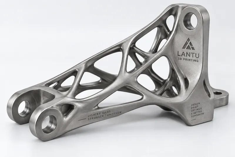
Introduction: Why Weight Reduction Is Becoming Harder—and More Important
In aerospace, robotics, and high-end equipment, every additional kilogram of structural weight often means several times the cost in energy consumption, heat dissipation, and inertia. Traditional weight reduction relies on experience-based hollowing and rib reinforcement, but when parts must satisfy multiple load cases and constraints, the margin left for manual design is quickly exhausted. Topology Optimization hands the question of "where to place material" over to mathematical solvers: within a given design space, load conditions, and constraints, it maximizes stiffness or minimizes compliance so that material appears only where it is truly needed.
The real turning point comes from 3D printing. Conventional subtractive manufacturing and mold-based processes struggle to economically produce the freeform surfaces and internal lattices commonly found in topology optimization results, while additive manufacturing is largely free from these geometric constraints. lantu3D defines topology optimization as a key link "from design intent to physical delivery," rather than merely a way to generate drawings.
1. Core Principles of Topology Optimization: Let Material Follow the Load
The mainstream approach uses the Solid Isotropic Material with Penalization method (SIMP): the design domain is discretized into a finite element mesh, and each element is assigned a relative density between 0 and 1. With volume fraction as a constraint—commonly 15%–30%—and minimum structural compliance as the objective, the solver iterates repeatedly. It continuously "erodes" low-stress regions and ultimately leaves behind a connected load-bearing skeleton.
In engineering practice, three boundaries must be observed: first, the minimum member size is typically set at 2–4 mm to avoid printing overly thin unsupported features; second, symmetry and draft constraints should be declared in advance, otherwise the result may not be suitable for post-processing; third, multiple load cases should be weighted to prevent optimization for a single load condition at the expense of other directions. In one collaborative robot forearm case, an aluminum alloy part with an initial wall thickness of 6 mm was reduced through topology optimization into a variable-section skeleton, cutting weight by approximately 38%.
2. Simulation-Driven Design Loop: From Density Cloud to Manufacturable Geometry
A topology result is a "density cloud," not a finished part. Implementation requires three reconstruction steps: first, shape-preserving smoothing is performed to remove checkerboard patterns and jagged edges using smoothing algorithms; second, minimum wall thickness and minimum hole/slot manufacturing constraints are applied to thicken hair-thin connections to printable thresholds—SLM metal parts are recommended to have solid wall thicknesses of ≥ 1.2 mm; finally, a process orientation check is conducted to record the optimal print orientation, ensuring that large overhang surfaces face downward and lattice struts grow as much as possible at 45° angles to reduce support structures.
The most easily overlooked step here is re-analysis: the smoothed geometry must be fed back into finite element analysis to confirm that stiffness loss remains within 5%. Before delivery, lantu3D compares the optimized part with the baseline design under the same operating conditions and provides comparison tables for displacement, stress, and safety factors, avoiding the situation where a part "looks lighter but is actually weaker."
3. 3D Printing Implementation: Lattices, Wall Thickness, and Parameters
At the manufacturing stage, topology-optimized skeletons are often combined with lattice infill: body-centered cubic (BCC) lattices with strut diameters of 2–4 mm and cell sizes of 8–15 mm are placed in non-primary load-bearing cavities, cutting an additional 20%–40% of weight with almost no stiffness loss. Metal parts use SLM (Selective Laser Melting). A process window with layer thicknesses of 30–40 μm, laser power of 200–370 W, and scanning speeds of 800–1200 mm/s can balance density—targeting ≥ 99.5%—and surface quality. Nylon parts use SLS, with powder bed temperature controlled at 170–175°C and layer thickness of 0.1–0.15 mm.
Support strategy determines post-processing cost: topology-optimized parts should be as self-supporting as possible, and regions with overhang angles greater than 45° can avoid supports. Where supports are necessary, lattice or tree-like supports are preferred to facilitate later removal while maintaining surface consistency.
4. Validation and Typical Application: A Drone Bracket with 35% Weight Reduction
Take an industrial drone motor bracket as an example: the original CNC aluminum part weighed 320 g, and under multiple load cases, its local stress concentration factor reached 2.7. After topology optimization, it was reconstructed as an SLM titanium alloy (Ti6Al4V) variable-section skeleton with local BCC lattices. The solid wall thickness was standardized to 1.5 mm, and the print orientation was set with the primary load axis vertical. Post-processing consisted only of sandblasting and anodizing. The final weight was 208 g, achieving a 35% weight reduction, while the first natural frequency increased by 12% and the fatigue safety factor rose from 1.4 to 2.1. The cycle from optimization to first-part delivery was approximately 9 days, far shorter than a mold-based solution.
5. Implementation Essentials and Pitfall Checklist
To make topology optimization truly practical, the following checklist is recommended: ① define real loads and boundaries clearly—it is better to apply fewer constraints than incorrect ones; ② start the volume fraction at 25% and tighten it gradually while observing the performance inflection point; ③ enable minimum member size and print orientation constraints during the optimization stage; ④ always perform re-analysis after smoothing, and return to the design loop if stiffness deviation exceeds 5%; ⑤ use lattices only in non-primary load-bearing areas, while keeping the main load paths solid; ⑥ after printing, conduct spot checks on critical dimensions and density—using CT or microscopy—to confirm there are no lack-of-fusion defects.
Conclusion
Topology optimization is not an "automatic drawing generator," but a process of encoding engineering judgment into the solver. Its true value is unleashed through the geometric freedom of 3D printing: placing every gram of material along the load path. lantu3D integrates topology optimization into a closed loop of "design—simulation—manufacturing—validation," helping companies turn lightweighting from a slogan into deliverable physical parts without sacrificing reliability.
Submit a model, drawing, image or written notes. Engineers will review material, process, finishing and delivery based on actual use.