
Introduction: Same Machine, Same Parameters—Why Do Parts Start Warping at the Edges After the 11th Build?
Metal laser powder bed fusion (LPBF) shops often encounter an anomaly that is difficult to attribute: the machine has passed annual calibration, the powder batch has not changed, and laser power and scan speed remain within their controlled windows, yet after the same build plate has been used for its 8th to 12th build, corner parts begin showing localized warping, first-layer recoating drag marks, or even cracking at the part-to-plate interface. Post-event reviews often label the cause as “parameter drift.” Recalibrating energy density may restore performance temporarily, only for the issue to recur two builds later. The actual root cause is often outside the parameter set: the build plate itself—the carrier on which parts are grown—is no longer the process tool with traceable geometry and stress conditions that it was when new. Wire cutting after each build, leveling by milling, stress relief, and repeated installation all consume remaining thickness, alter flatness and residual-stress distribution, and leave localized bonding defects. Treating the build plate as a “permanent machine accessory” allows a continuously degrading variable to remain outside the controlled process list.
1. Define the Boundary First: Build-Plate Condition Is Neither Machine Geometric Accuracy Nor Consumable MTBF
Three frequently conflated layers must first be distinguished. Machine geometric-accuracy inspections—laser interferometry, ballbar testing, positioning and repeatability, and machine-table leveling compensation tables—measure motion axes and installation datums, with acceptance criteria documented in annual calibration reports. Wear-item and spare-part lifecycle management—protective windows, recoater blades, filter elements, and seals—measures replaceable items that are changed based on MTBF or differential-pressure thresholds. Build-plate condition management, however, concerns a process carrier that is repeatedly machined and reused, but is not discarded as a complete item on a fixed replacement interval: every cycle removes a layer of material by milling, thickness decreases unidirectionally, and flatness and stress condition are redistributed according to the cutting and thermal history. The first two layers answer “Is the machine still accurate?” and “Should this component be replaced?” This layer answers “How much machinable allowance remains on this carrier, and why is it permitted to continue supporting parts for this build?” A platform that assumes full lifecycle responsibility from drawing to physical delivery must make the carrier’s condition chain traceable at the individual-item level, just like the part, powder, and parameter package, rather than relying on operator memory.
2. Break Down “Can It Still Be Used?” into Five Assessable Fields
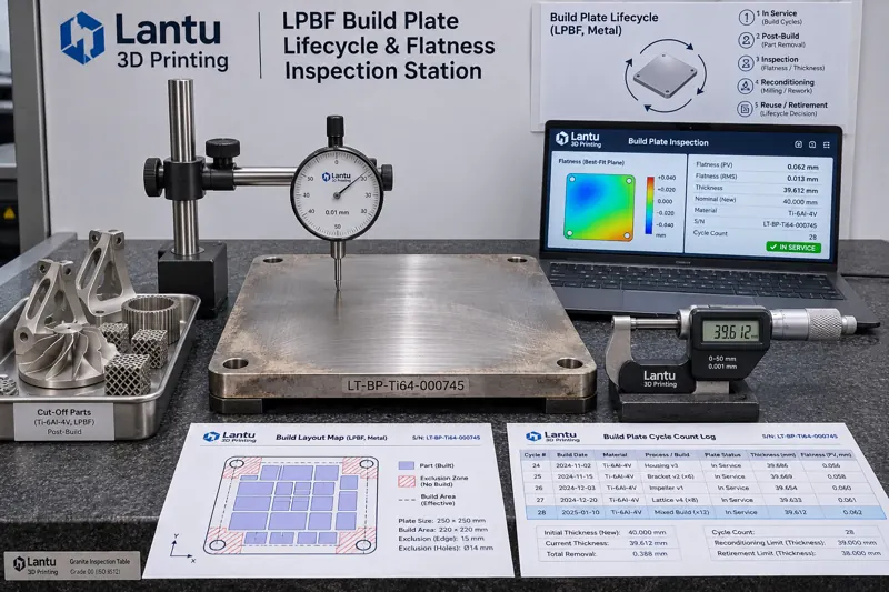
Each build plate should be assigned a unique ID consisting of material grade, heat lot, commissioning date, and serial number. Release for each machine installation should then be condensed into a five-field status card: remaining thickness T_rem (calculated as original plate thickness T0 minus cumulative milling removal ΣΔ; verified by taking the minimum of three- or five-point micrometer measurements); working-surface flatness F (peak-to-valley variation measured after leveling milling with a dial indicator or CMM on a 100 mm grid); cumulative use count N and cumulative thermal-cycle hours H (layer count, preheat temperature, and hold time for each build are automatically captured); residual-stress and warpage trend (the rate of change in F across three cycles at the same measurement points, ΔF/ΔN); and local bonding history (maps of prior part-cutting locations, coordinates where bonding cracks or lack of fusion occurred, and weld repair or grinding records). The first three fields provide hard thresholds, while the latter two provide trends and no-build zones. If any field lacks a record, the plate is classified as “pending review” for that installation rather than released by default.
3. Thickness and Flatness: Define Thresholds Rather Than Relying on “It Still Feels Flat”
For a typical 250 × 250 × 25 mm Ti6Al4V or 316L build plate, engineering acceptance criteria may be defined as follows: T_rem must not fall below the minimum thickness T_min required for machine clamping and the Z-axis datum. T_min is typically set at 60%–70% of T0; for example, a 25 mm plate may have a hard lower limit of 16 mm. Once below T_min, the plate is retired and must not be extended on the basis that “one more milling pass may still work.” Material removal per leveling operation, Δ, should be controlled to 0.20–0.35 mm. Any single removal exceeding 0.50 mm requires documented justification and a repeat stress assessment. Working-surface flatness F should preferably be ≤0.05 mm/250 mm, and ΔF between two adjacent cycles should be ≤0.02 mm. Otherwise, stress relief must be performed and flatness remeasured before installation rather than placing the plate directly back into service. Heated build plates also require verification of contact with the heating surface: localized poor contact can cause actual preheat temperatures to be 20–40 °C below the setpoint, resulting in unstable first-layer bonding on corner parts within the same build. All values should be documented in version-controlled technical requirements, such as BP-SPEC-003 rev.C, jointly approved by process engineering, quality, and equipment teams. Thresholds vary by material and machine model and must not be transferred across machine platforms.
4. Cycle Logs and No-Build Zones: Prevent Defects from the Previous Build from Reaching the Next
A build plate is not simply “a flat plate”; it is a map with historical coordinates. After parts are cut off following each build, the log should record that build’s layout: part bounding boxes, support contact points, wire-EDM paths, and locations where bonding cracks or lifting occurred. When nesting the next build, these locations should be designated as no-build zones, expanded by at least 10 mm. If an anomaly occurs twice consecutively at the same location, the plate must be withdrawn from service and subjected to liquid penetrant or ultrasonic inspection. The log should also link four types of evidence: powder batch number and blend ratio for the build, controlled parameter-package version and hash, original oxygen-content and preheat-curve data points, and post-cutting flatness measurement records. This enables a response to a customer asking, “On which plate was this delivered part built, and on which plate cycle?” The part serial number can be traced back to the build-plate ID, cycle number N, T_rem and F values at the time, and approval records, rather than producing only a compliant final inspection report. Alongside inspection lots, witness coupons, and material certificates, the build-plate cycle card is the fourth category of carrier evidence in the delivery evidence package.
5. Machine-Installation Release Gates and Retirement Criteria (D1–D5)
These fields should be formalized into five sequential release gates: D1 Identity—the build-plate ID is legible, material and machine model are compatible, and no cross-platform borrowing has occurred; D2 Geometry—T_rem ≥ T_min and F ≤ 0.05 mm, with measurement-point records including valid calibration status for the measuring instruments; D3 History—N, H, and ΔF/ΔN remain within controlled trends, and no-build zones have been synchronized with the current build layout; D4 Stress and Cleanliness—stress relief has been completed and reverified where necessary, and the working surface is free of residual powder, cutting-fluid residue, and undocumented weld-repair areas; D5 Sign-Off—the process engineer reviews the plate, quality releases it, and the equipment technician confirms clamping and preheat contact, with timestamps from all three entered in the log. If any gate is not passed, the build plate is labeled “quarantined” and removed from production scheduling. Retirement is based not on “years in use” but on condition: T_rem reaches its lower limit, F remains out of tolerance after two remeasurements, defects recur at the same location, or a through-thickness crack appears. Any one of these conditions requires scrapping, with final thickness and photographs retained; the identification number must never be reused.
6. Common Failure Modes and an Implementation Checklist
The four most common pitfalls are: first, tracking only “number of uses” while ignoring “remaining thickness”; two plates with the same N may differ in remaining stiffness by a factor of two because of different milling removal. Second, installing the plate immediately after milling without rechecking flatness, thereby carrying taper introduced by the leveling operation itself into the next build. Third, recording build-plate anomalies on machine maintenance tickets, making carrier history unavailable through part-serial-number traceability. Fourth, storing retired and active plates together, allowing an ID to be reassigned to a new plate. Implementation should begin with a minimum closed loop: first, assign IDs and conduct one baseline measurement for all active plates, including T_rem, F, N, and photographs; then make “build-plate ID + cycle number” mandatory fields in production scheduling and build-layout documentation; finally, turn D1–D5 into a one-page checklist that travels with each build. After three months, review first-layer defect rate, warpage rework rate, and unplanned plate-change frequency, using the data to adjust thresholds rather than revising the specification annually based solely on experience.
Conclusion
Build plates are among the few controlled objects in the LPBF process chain that are permanently altered with every use. Separating them from the ambiguous category of machine accessories and managing them through identification, remaining thickness, flatness, thermal-cycle history, no-build zones, and five installation release gates transforms first-layer bonding and warpage anomalies from parameter-tuning guesswork into traceable, assessable, and predictable release decisions. For a platform assuming full responsibility from drawing to physical delivery, the completeness of the carrier condition chain is as much a part of delivery quality as parameter packages, powder batches, and inspection records: if the part must be traceable, the plate on which it was formed must be traceable as well.
Submit a model, drawing, image or written notes. Engineers will review material, process, finishing and delivery based on actual use.