
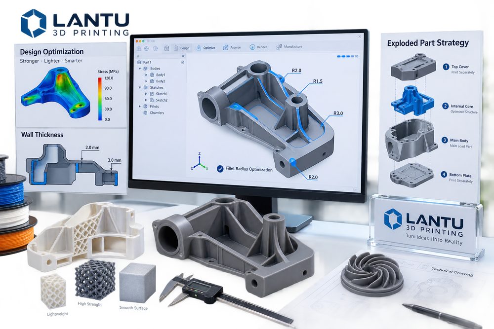
Introduction: The Design Stage Determines Most Manufacturing Risks
3D printing gives product development a great deal of freedom, but freedom does not mean the absence of constraints. Many projects fail not because the equipment is incapable, but because the model has not considered manufacturing logic in advance with respect to wall thickness, fillets, holes and slots, overhangs, powder removal, assembly, and inspection datums. A model may work on screen, but that does not mean it will remain stable in a powder bed, resin vat, or metal forming process.
In project evaluations, lantu3D has found that the earlier design optimization is introduced, the lower the rework cost. A single effective DFAM review can often reduce support marks, warping, breakage, incomplete powder removal, assembly interference, and post-processing difficulty, allowing 3D printing to truly support R&D iteration and on-demand delivery.
1. Wall Thickness Is Not Better When It Is Thinner
Thin walls can reduce material usage, but excessive thinness can lead to warping, damage, and post-processing failure. Safe wall thickness varies by process: resin parts must account for brittleness and curing deformation, SLS nylon parts must consider thermal shrinkage in large thin walls, and metal parts must account for thermal stress and support removal. For load-bearing structures, simply increasing the shell thickness is not always optimal; adding ribs, honeycomb, or lattice structures often achieves a better balance between weight and stiffness.
During design, external walls, functional walls, and process walls should be distinguished. External walls focus on surface quality, functional walls carry load and support connections, and process walls are used for support clamping or protection during post-processing. Setting all wall thicknesses uniformly can easily lead to areas that are too strong, too weak, or unnecessarily costly.
2. Fillets and Transitions: Reduce Stress Concentration and Post-Processing Difficulty
Sharp corners, thin roots, and abrupt section changes are prone to stress concentration. For resin and nylon parts, appropriate fillets can reduce chipping during transport and assembly; for metal printed parts, fillets can also improve heat conduction paths and lower the risk of cracking and warping. Internal right angles also make powder removal, sanding, and painting more difficult, especially in deep cavities and at intersecting rib locations.
Fillets are not better simply because they are larger. Excessive fillets may interfere with assembly boundaries or the intended visual form, so they should be determined based on load paths, contact surfaces, and machining allowance. For surfaces that require secondary machining, fillets must also avoid interfering with tool paths and fixture positioning.
3. Holes, Slots, and Threads: Think About Forming Before Assembly
Small holes, deep holes, transverse holes, and blind slots are high-risk areas in 3D printing. If the diameter is too small, powder, resin, or support residues may block the feature; holes with excessive depth-to-diameter ratios are also difficult to clean. For precision hole locations, it is recommended to leave undersized pilot holes for drilling, use threaded inserts, heat-set brass inserts, or post-machined threads rather than relying entirely on one-step printed formation.
Assembly clearance should be set according to the material and post-processing method. Snap-fit clearances after resin painting, sliding-slot clearances after nylon dyeing, and locating clearances after metal sandblasting may all change. The drawing should clearly define critical mating surfaces to prevent post-processing staff from accidentally sanding or coating the wrong area.
4. Part Splitting Strategies: Not a Compromise, but an Engineering Choice
Monolithic printing can reduce assembly, but it is not always the best option. Large thin-walled parts, complex deep-cavity parts, models with high visual requirements, and products needing multi-material effects are often better suited to split-part printing. Proper part splitting can optimize build orientation, reduce support marks, shorten print time, improve surface quality, and reduce losses caused by a single-part failure.
When splitting parts, positioning features and hidden seams should be designed in. Common methods include tenons and slots, locating pins, magnets, screws, stepped bonding joints, and seam masking with decorative lines. For display models, seams should avoid the main visual focus; for functional parts, joints should avoid the main load path. Part splitting must also consider subsequent packaging and transportation to avoid damage to slender structures during logistics.
5. Create Design Outputs That Can Be Inspected
A good 3D printing design should not only be printable, but also inspectable. In addition to the model file, it is recommended to provide a key dimension table, surface annotations, material performance requirements, color requirements, assembly relationships, and acceptance priorities. If only an STL file is provided, the supplier can only judge based on experience, which increases communication cost and the probability of rework.
In project collaboration, lantu3D connects design review, material recommendations, process selection, post-processing plans, and delivery inspection. In this way, customers see not just a printing quote, but a risk-control solution that spans from requirements to the final physical part.
Conclusion
The essence of design optimization for 3D printing is to bring manufacturing constraints into modeling decisions early. By using appropriate wall thickness, fillet transitions, hole and slot treatment, part splitting strategies, and inspectable outputs, companies can significantly reduce print failure rates, post-processing costs, and delivery uncertainty, allowing 3D printing to move from “can be made” to “can be made reliably.”
Submit a model, drawing, image or written notes. Engineers will review material, process, finishing and delivery based on actual use.