
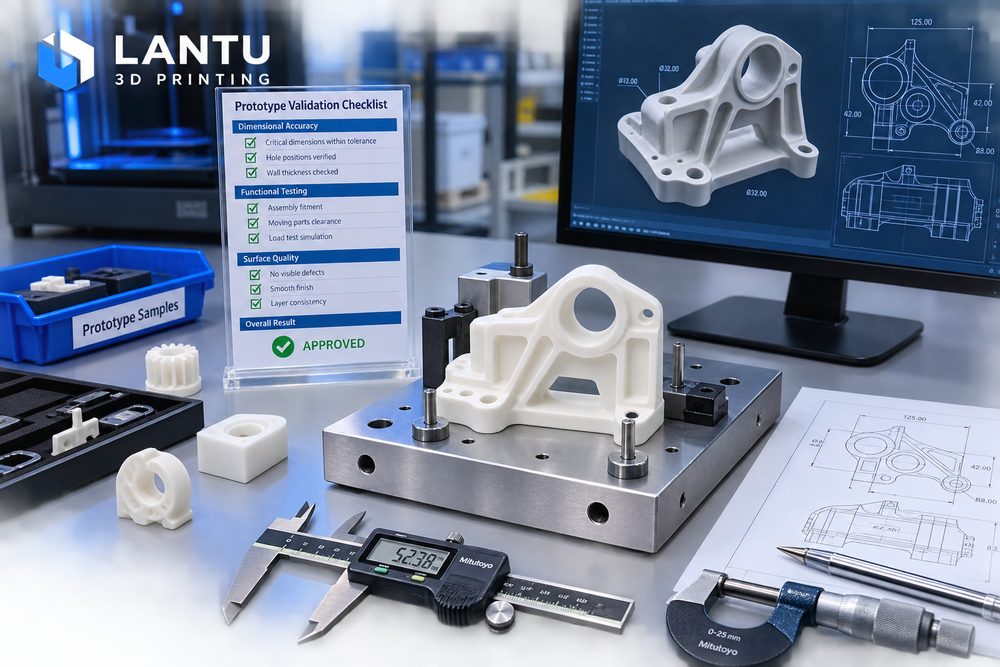
Introduction: Sample validation is not just “print one and see”
Many R&D teams use 3D printing for prototyping because it quickly turns digital models into tangible parts. But if the validation process stops at appearance approval, the sample can easily lead to misleading conclusions: a shape that looks correct does not mean assembly will fit, assembly fit does not guarantee long-term functional reliability, and success with a single part does not mean stable small-batch production.
The core of sample validation is to eliminate the most critical engineering risks in the fewest prototype iterations possible.
Blueprint3D treats each sample as a validation checkpoint between the design blueprint and the physical deliverable. Every sample should answer a clear question, such as “Can this snap fit withstand 20 assembly cycles?”, “Does the hole spacing meet assembly tolerance?”, or “Does the surface texture meet presentation requirements?” Only when the question is clear does the validation result have decision-making value.
1. Validation goals: define what the sample must prove first
Before making a sample, divide the validation goals into appearance, structural, assembly, functional, and manufacturability categories. Appearance focuses on form, proportions, surface texture, color, and feel; structural validation focuses on wall thickness, ribs, sharp corners, and deformation; assembly validation focuses on hole positions, snaps, threads, inserts, and clearances; functional validation focuses on load-bearing, temperature resistance, sealing, or motion; manufacturability focuses on whether the part is suitable for later small-batch production.
For example, for an electronic device enclosure, the first prototype may only verify grip size and interface locations, so a high-precision SLA resin is sufficient. If the second round needs to verify repeated snap-fit assembly and disassembly, the material should switch to a tough resin or SLS nylon. If the third round is intended for small-batch trial production, surface finishing, assembly takt time, and packaging protection must be validated. Different goals require different materials and processes, so one sample cannot answer every question.
2. Process selection: match the sample’s capability to the validation question
SLA is suitable for high-detail appearance, transparent parts, and complex surface verification. Typical layer thickness is 0.05-0.1 mm, but its brittleness and heat resistance may not represent the final injection-molded part. SLS nylon is suitable for snap fits, hinges, thin-wall housings, and functional structure validation. Common PA12 materials offer good toughness and wear resistance, but the surface has a powdery texture. FDM is suitable for large, low-cost structural validation, but layer lines and anisotropy are obvious. Metal SLM is suitable for high-strength or high-temperature applications, but cost and lead time are higher.
Process selection should be written into the validation plan, not explained after the fact. For example: “This round uses SLS PA12 to validate snap-fit elasticity; final appearance color is not evaluated.” This prevents customers from mistaking a powder-like surface for a design failure and helps the engineering team focus on key metrics.
3. Appearance and dimensional inspection: replace subjective judgment with measurable standards
When the sample arrives, first inspect appearance integrity, including material shortage, warping, cracks, support marks, layer lines, color variation, and contamination. Then measure the key dimensions. It is recommended to mark 5-15 critical points on the drawing, such as overall length, hole spacing, assembly face thickness, snap height, and interface window position. For ordinary appearance samples, ±0.3 mm can be used as an initial reference, while precision assembly parts should follow stricter standards based on process capability and customer requirements.
Dimensional inspection should not only record “pass/fail”; it should also record the direction of deviation. If multiple holes shift in the same direction, the cause may be the model coordinates, print orientation, or post-processing clamping. If thin-wall areas consistently shrink, it may relate to material curing, cooling, or wall thickness design. Deviation direction is often more useful than a single numeric result when planning the next revision.
4. Assembly testing: from static fit to repeated use
Assembly validation includes insertion, rotation, snap fit, screw fastening, insert installation, and compatibility with standard components. For snap-fit structures, perform at least 10-20 repeated assembly/disassembly cycles and observe whitening at the root, breakage, or insufficient spring-back. For screw bosses, confirm pilot hole diameter, wall thickness, and fastening torque. If heat-set inserts are planned, also verify insert temperature, press-in depth, and surrounding deformation.
Common issues include insufficient clearance causing overly tight assembly, support points located on mating surfaces causing interference, thin walls deforming during support removal, and hole diameters shrinking due to resin shrinkage. The solution is not simply to “make it a little larger,” but to establish clearance rules based on the process. For example, SLS nylon moving fits should allow 0.3-0.5 mm clearance, while small holes in SLA appearance parts may be drilled later or compensated appropriately in the model.
5. Functional testing: turn the use case into executable actions
Functional validation should simulate real usage conditions. Load-bearing parts need loading tests, moving parts need cycle tests, housings need drop or compression risk assessment, and temperature-sensitive parts need environmental testing. Test conditions must be clearly defined, including load weight, duration, number of cycles, temperature range, and acceptance criteria. A vague statement such as “it feels strong enough” cannot support engineering decisions.
For example, a fixture sample that must withstand 5 kg of clamping force while maintaining positioning accuracy can be tested in three steps: static load of 5 kg for 30 minutes, 100 repeated clamping cycles, and a requirement that key hole deviations before and after testing do not exceed 0.2 mm. If the sample fails, record the fracture location, force direction, and failure time, then determine whether the cause is insufficient material, insufficient wall thickness, or stress concentration in the structure.
6. Iteration records: make every sample round traceable
After validation, create an iteration record that includes version number, validation goals, material and process, test results, issue list, revision recommendations, and the next decision. Each issue should be linked to a model location and an action item. For example: “The power interface window is shifted 0.4 mm to the right; in design file V2, move the window 0.4 mm to the left and add a 0.5 radius fillet.”
When a project is approaching small-batch production, it is best to keep one approved sample as the benchmark and document the key validation conclusions in the production instructions. In this way, the production team receives more than just a model file—they also understand which dimensions must be controlled closely, which surface requirements are acceptable, and which post-processing steps must not be skipped.
Conclusion
An effective 3D printed sample validation process should start with clear validation goals, match the right material and process, quantify appearance and dimensional inspection, carry out assembly and functional tests, and preserve iteration records. By connecting samples, data, process, and delivery, Blueprint3D helps customers reduce ineffective trial-and-error and brings each prototype closer to a manufacturable physical solution.
Submit a model, drawing, image or written notes. Engineers will review material, process, finishing and delivery based on actual use.