
Introduction: Design optimization is the first battlefield for reducing 3D printing costs
In many 3D printing projects, cost issues do not arise at the machine stage; they are hidden in the model design phase. Walls that are too thick increase material use and print time, while walls that are too thin can lead to deformation and breakage. Enclosed cavities make powder removal difficult, and excessive large-area overhangs increase support and post-processing costs. In the workflow from blueprint to physical delivery, lantu3D treats design optimization as the first engineering review after project kickoff.
Unlike traditional manufacturing, 3D printing allows complex surfaces, internal channels, lattices, and integrated structures, but freedom does not mean the absence of constraints. Different processes have different requirements for minimum wall thickness, hole diameter, clearance, support angle, and surface quality. A model suitable for an SLA presentation may not be suitable for SLS functional validation, and a topology-optimized structure designed for metal printing may still require CNC finishing and assembly datums.
1. Work backward from the functional goal to the design parameters
Design optimization should begin with a clear definition of the part’s purpose: appearance display, assembly verification, strength testing, or low-volume end-use production. Appearance parts should prioritize surface continuity, support placement, and paint finish; assembly verification parts should focus on hole locations, snap-fits, shafts, and fit clearances; strength testing parts should consider print orientation, interlayer bonding, reinforcement ribs, and load paths. Different goals require different optimization directions.
For example, for an SLS PA12 snap-fit part, a common recommended wall thickness is 1.2-2.0 mm, and a moving clearance can start from 0.3-0.5 mm for validation. SLA appearance parts show finer detail, but thin snap-fits can become brittle after repeated bending. For metal SLM parts with threads and high-precision holes, machining allowance is usually reserved and post-print finishing is applied. Bringing these parameters forward prevents the part from being discovered as unassemblable only after printing is complete.
2. Balancing lightweighting and strength
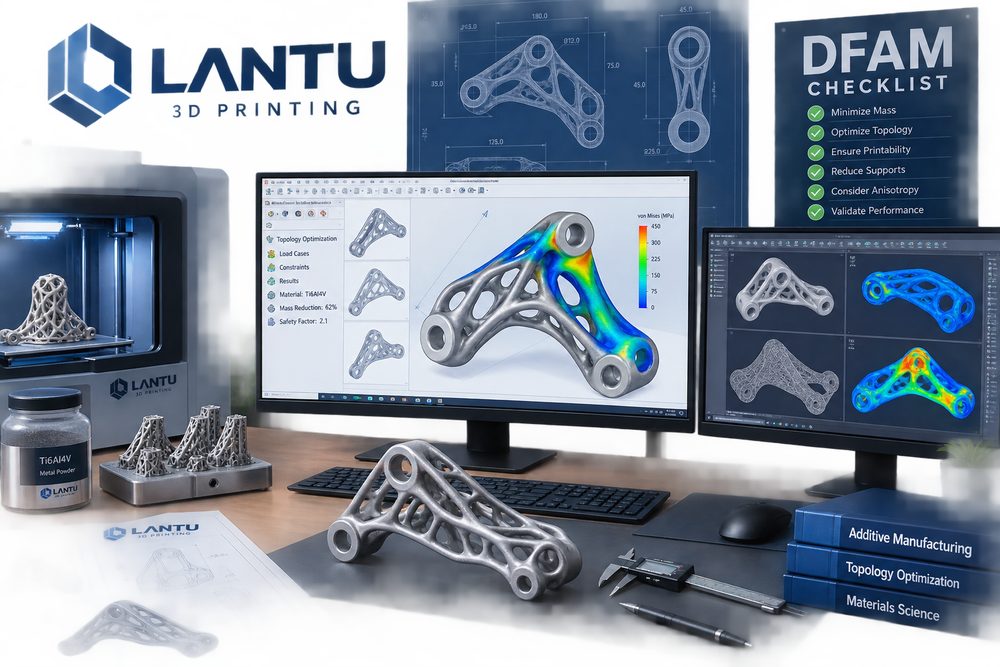
Lightweighting does not simply mean hollowing out a part. For load-bearing components, the load path should be analyzed first, and then the weight reduction zones should be determined. Common methods include adding fillets to reduce stress concentration, using ribs instead of overall thickening, reducing mass through lattice structures, and integrating multiple assembled parts into a single component. Topology optimization results also require secondary engineering refinement to ensure minimum strut diameter, powder removal channels, and accessibility for post-processing tools.
In real projects, some enclosure parts have reduced material usage by about 20%-35% while maintaining stiffness by replacing solid thick walls with a uniform 2 mm wall and local reinforcement ribs. However, if a rib connects directly to a cosmetic surface, it may create sink marks or visible shading. If lattice openings are too small, SLS powder or metal powder cannot be removed, creating hidden risks instead. Therefore, optimization must consider both manufacturability and inspection.
3. A process-oriented model check list
Before printing, check whether the model contains non-manifold edges, reversed normals, overlapping surfaces, overly thin walls, isolated small features, or sealed cavities. For SLA parts, check whether supports will land on primary appearance surfaces; for SLS parts, check the minimum hole diameter and powder removal path; for FDM parts, check how print orientation affects layer lines and strength; for metal parts, check support removability, thermal deformation risk, and machining datums.
lantu3D commonly reviews models by classifying issues into three categories: “must modify,” “recommended optimization,” and “acceptable risk.” Must-modify items include parts that cannot be formed, cannot be depowdered, have insufficient wall thickness, or have critical holes that are unreachable. Recommended optimizations include chamfers, fillets, weight reduction, and support-face adjustments. Acceptable risks must be confirmed with the customer before delivery, such as the reproduction level of fine textures.
4. A collaborative workflow for design optimization
Efficient design optimization is not one-way drawing revision, but a closed loop between design, process, quotation, and delivery. The first step is to confirm the use case and acceptance criteria, the second is to select candidate processes and materials, the third is to perform a DFAM check, the fourth is to provide revision suggestions and risk notes, and the fifth is to proceed to printing after customer confirmation. For complex projects, it is often effective to print partial validation samples first to verify snap-fits, textures, wall thickness, or assembly relationships at lower cost.
This workflow reduces the likelihood of having to rework the entire part and helps customers understand where costs come from. In many cases, reducing one large support area, adjusting the direction of one hole, or splitting one difficult-to-handle structure can significantly lower post-processing difficulty and shorten the delivery cycle.
Conclusion
Design optimization is the core stage for unlocking the value of 3D printing. lantu3D emphasizes starting from requirements, materials, processes, structure, and delivery standards so that models are not only printable, but can also reliably pass assembly, appearance, and functional verification. Doing the optimization up front is the real way to cut costs, shorten lead times, and improve delivery certainty.
Submit a model, drawing, image or written notes. Engineers will review material, process, finishing and delivery based on actual use.