
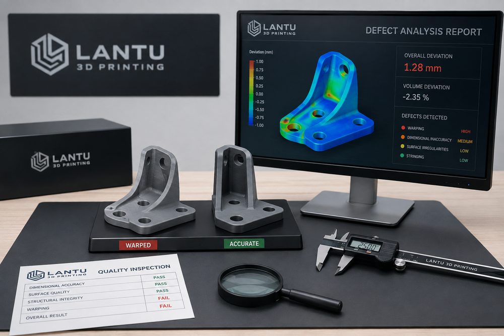
Introduction: Defect Analysis Helps 3D Printing Move from Experience to Control
Failed builds and quality fluctuations in 3D printing are not uncommon, but what really matters is whether the root cause can be identified quickly and a prevention mechanism can be established. Warping, cracking, interlayer delamination, voids, surface particles, dimensional deviation, and support marks may all come from materials, models, equipment, parameters, environment, or post-processing. Bluprint 3D incorporates defect analysis into project lifecycle management so that a single failure can be turned into practical experience for more stable future delivery.
If defects are simply attributed to “an unstable printer,” the problem often cannot be solved. For example, the same type of deformation may be related to curing shrinkage and support layout in SLA, cooling curves and part placement in SLS, build plate adhesion, infill, and ambient temperature in FDM, and residual stress and scanning strategy in metal SLM. Defect analysis requires step-by-step troubleshooting based on evidence.
1. Common Defects and Typical Causes
Warping is usually related to material shrinkage, thermal gradients, and insufficient support. If the ambient temperature for ABS in FDM fluctuates greatly, corner lifting can easily occur; if a nylon SLS part cools too quickly, a large flat structure may show slight bending; if a long metal part does not have proper support and heat treatment, datum shift may also occur. Cracking and interlayer delamination are often related to interlayer bonding, print orientation, and load path.
Surface defects include layer lines, particles, support scars, coating runs, and powder residue. Excessively dense supports on SLA parts increase finishing work, while too few supports may cause local deformation; SLS parts naturally have a powdery surface texture and usually require sandblasting or tumbling to improve it; metal printed surfaces are relatively rough, and if sealing or sliding fit is required, machining or polishing is usually necessary.
2. Troubleshooting Dimensional Deviation
Dimensional deviation should first be divided into overall scaling deviation, local deformation deviation, and deviation introduced by post-processing. Overall deviation may come from machine calibration, material shrinkage compensation, or slicing parameters; local deviation may be related to support, placement orientation, and heat concentration; post-processing deviation is often caused by sanding, coating, heat treatment, and insert installation. Measuring only one dimension is not enough to explain the issue; key holes, datum surfaces, thin walls, and long-span areas should be compared instead.
It is recommended to build a record table for “model dimensions, post-print dimensions, and post-processing dimensions.” If the deviation already exists after printing, focus on process and equipment; if the deviation appears only after post-processing, focus on coating thickness, sanding amount, or heat-treatment deformation. For assembled parts, plug gauges, calipers, coordinate measuring machines, or 3D scanning can be used for verification depending on the accuracy requirements of the project.
3. From Defects to Corrective Actions
Corrective actions should include both temporary remediation and long-term prevention. Temporary remediation is used to save the current delivery, such as local filling, recoating, enlarging holes, repairing inserts, or reprinting key parts. Long-term prevention requires modifying the model, adjusting placement orientation, optimizing support, changing materials, updating parameters, or adding intermediate inspections. For recurring defects, a project knowledge base should be established instead of relying on one engineer’s memory.
For example, if a thin-walled housing repeatedly shows corner deformation, the measures can be divided into three layers: at the design level, add fillets and local ribs; at the process level, change the placement orientation and add supports; at the inspection level, measure key edge distances before and after support removal. With multi-layer control, the defect rate usually drops more easily than by simply improving print accuracy.
4. Risk Transparency in Customer Communication
Defect analysis is not only an internal quality tool but also a customer communication tool. For prototype parts, moderate defects may not affect validation goals; for display parts, minor surface flaws may be unacceptable; for functional parts, good appearance does not necessarily mean reliable strength. Therefore, acceptance criteria should be clearly defined before delivery: which dimensions are critical, which surfaces are class-A cosmetic surfaces, and which areas may allow support marks or powder texture.
Bluprint 3D recommends providing risk notes and validation suggestions for complex projects, such as making small samples, local cross-section parts, or material test coupons first. This reduces customer decision risk and avoids exposing all issues only at the final delivery stage.
Conclusion
The value of defect analysis lies in building a closed loop that is traceable, verifiable, and reusable. By linking materials, models, processes, equipment, post-processing, and inspection, Bluprint 3D helps customers move from one-off sample making to more stable engineering delivery. Defects cannot be eliminated entirely, but they can be identified, controlled, and transformed into certainty for the next project.
Submit a model, drawing, image or written notes. Engineers will review material, process, finishing and delivery based on actual use.