
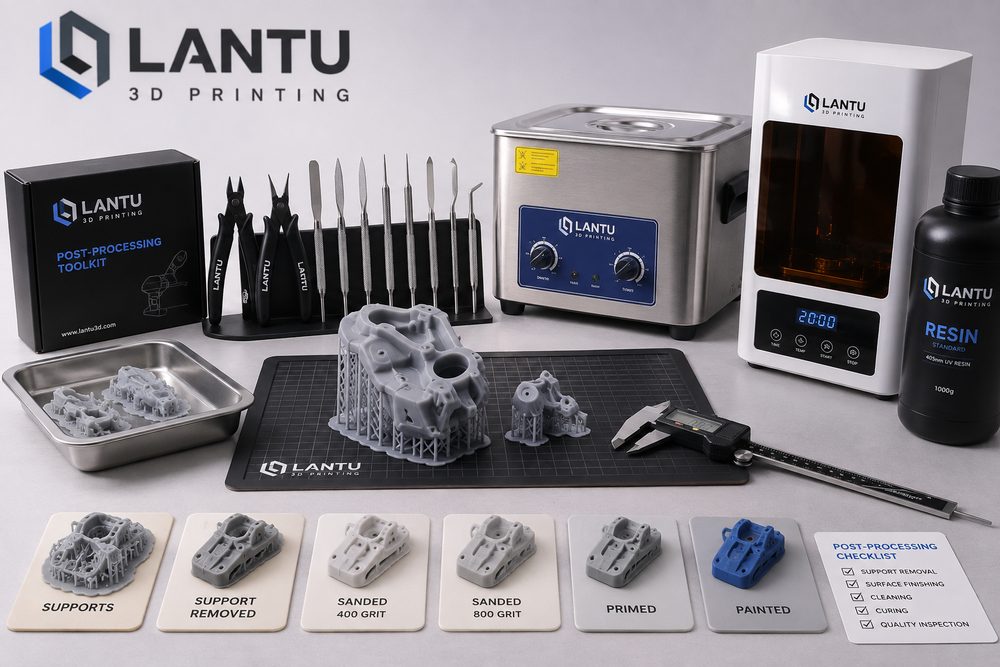
Introduction: Why Post-Processing Often Determines Whether a Part Can Truly Be Delivered
In many enterprise 3D printing projects, finishing the print is only a middle step in the delivery chain. What the customer actually accepts is an end-use part that can be assembled, displayed, tested, and traced—not a raw piece straight off the machine. Taking SLA photopolymer, SLS nylon, and metal SLM parts as examples, as-printed parts often have support marks, residual powder, layer lines, burrs, local warping, or uneven surface color. If post-processing lacks a standard workflow, the same batch of parts can end up with visual differences, dimensional drift, and inconsistent assembly feel, ultimately affecting project acceptance.
lantu3D places greater emphasis on full lifecycle management from concept/design to physical delivery, so post-processing is not an “extra step after printing” but part of the manufacturing plan. A mature project will define post-processing targets during quoting, process review, and DFM, such as surface roughness Ra 3.2–6.3 μm, key hole tolerance of ±0.15 mm, no obvious support break marks on visible surfaces, and acceptable color variation across dyed batches. Only by setting these metrics up front can post-processing become a controlled engineering process rather than a repair action that depends on technician experience.
1. Support Removal and Powder Removal: Preventing Structural Damage from Entering the Next Step
SLA, DLP, and metal SLM parts typically require support structures, while SLS nylon parts require powder removal. Support removal may seem simple, but it directly affects visible surfaces and the integrity of thin-walled structures. For resin parts with wall thickness below 1.2 mm, if support points are placed on visible faces or load-bearing edges, removal can easily cause whitening, chipping, and microcracks. A better approach is to distinguish A-surfaces, B-surfaces, and hidden areas during design review, concentrate support marks in areas that can later be sanded or are not visible, and control both the diameter and density of support contact points.
For SLS nylon parts, powder removal focuses on blind holes, deep grooves, lattices, and internal channels. If PA12 powder remains inside cavities, it can affect assembly, weight, and the uniformity of later dyeing. In production, a combination of compressed air, vibration-assisted depowdering, soft brushing, and ultrasonic assistance can be used. For long narrow channels or complex cavities, powder escape holes should be reserved during the design stage; a diameter below 3–5 mm is generally not recommended. Before delivery, the part should be verified by weighing, borescope inspection, or airflow testing to confirm that powder has been removed effectively.
2. Washing and Secondary Curing: The Key to Stable Photopolymer Part Performance
After a photopolymer part is removed from the build platform, uncured resin often remains on the surface. Insufficient cleaning leads to tacky surfaces and poor paint adhesion; excessive cleaning can cause liquid absorption, swelling in thin sections, or brittleness risks. A common workflow uses isopropyl alcohol or a dedicated cleaning solution in staged cleaning steps, with soak time controlled according to part size. For small precision parts, a single cleaning cycle is usually limited to 3–8 minutes, followed by a rinse in fresh solution to reduce residual contamination.
Secondary curing affects hardness, heat resistance, and dimensional stability. If curing time, light intensity, or temperature are too high, resin parts may shrink more; if curing is insufficient, long-term strength and chemical resistance will be unstable. In engineering projects, curing parameters should be written into the process card, for example 405 nm UV, 40–60°C, 10–30 minutes, and verified according to the material supplier’s recommendations. For assembled parts, critical dimensions should be sampled before and after curing to record shrinkage trends so that future print compensation can be corrected.
3. Surface Finishing: From Layer Line Improvement to Functional Surfaces
Surface finishing is not only about looking better. Sandblasting, tumbling, hand sanding, chemical vapor smoothing, polishing, painting, electroplating, and dyeing all change the coefficient of friction, coating adhesion, sealing performance, and tactile feel. SLS PA12 parts can be sandblasted to remove loose powder and create a uniform matte surface, improving the typical rough powdery feel to a more even texture. Resin parts can be wet-sanded through multiple grit levels and filled with primer to meet display model and appearance validation requirements. Metal SLM parts may require heat treatment, machined datum faces, shot peening, or polishing to obtain functional surfaces.
It should be noted that every surface treatment can introduce dimensional changes. For example, sandblasting can slightly erode thin edges; painting adds a film thickness of tens to hundreds of microns per side; and electroplating also changes clearance in mating features. Therefore, for assembled parts and snap-fit parts, it is not enough to design only according to theoretical dimensions in the CAD model. Post-processing additions and reductions must also be included in tolerance chain analysis. In project reviews, lantu3D typically marks appearance surfaces, mating surfaces, and datum surfaces separately to avoid applying the same finishing standard to every area.
4. Dimensional Reinspection and Batch Consistency: Replacing Experience with Data
After post-processing, quality judgment should not rely on the naked eye alone. For functional parts, inspection items should be defined according to the drawing and intended use: calipers for length, width, height, and hole spacing; pin gauges for hole diameters; thread gauges for threads; and a CMM or 3D scan for complex surfaces. For critical dimensions within ±0.10 mm, relying only on standard handheld tools is risky; fixtures, dedicated gauges, or CMM verification should be used together. At least the first part, last part, and key locations should be sampled from each batch and recorded.
Batch consistency also includes color, gloss, texture, and marking. Dyed PA12 parts are especially prone to batch color differences, which may be caused by differences in powder lot, pre-cleaning quality, dye concentration, temperature, and time. A practical method is to process same-color parts from the same project together, record the dyeing temperature, time, and bath ratio, and keep a color chip or first article as a reference. For brand display parts, color tolerance should be clearly defined in the delivery standard rather than described vaguely as simply “black” or “gray.”
5. Project Management: Bringing Post-Processing into Schedule, Cost, and Risk Planning
Post-processing is often the most underestimated part of lead time. A batch project may take only 24 hours to print, but depowdering, curing, sanding, painting, inspection, and packaging may require 2–5 days. If outsourced coating, electroplating, or heat treatment is involved, production scheduling and rework windows must also be considered. When quoting and planning, project managers should break post-processing into traceable milestones and add buffers for critical steps to avoid the mistaken assumption that “printing is done, so delivery is imminent.”
In terms of cost, post-processing labor may account for more than printing itself, especially for display parts, transparent parts, and parts with high appearance requirements. Effective practices include reducing inaccessible dead corners in the design stage, avoiding unnecessary high-precision requirements, differentiating visible and non-visible surfaces, and confirming appearance standards with sample parts. For projects where customer requirements are still unclear, it is advisable to deliver a small batch of process samples first, confirm feel, color, and surface quality, and then move into mass production.
Conclusion: Standardized Post-Processing Is the Turning Point for 3D Printing to Become Stable Manufacturing
3D printing post-processing determines the gap between “being able to print a part” and “being able to deliver it consistently.” Support removal, depowdering, washing, curing, surface finishing, and reinspection all affect appearance, dimensions, strength, and customer experience. When choosing a 3D printing service, companies should pay attention to whether the supplier has process review capabilities, recorded post-processing parameters, quality inspection, and batch traceability. The value of lantu3D lies in managing design, manufacturing, post-processing, inspection, and delivery within a single lifecycle chain, enabling customers to receive physical results that are predictable, reviewable, and continuously optimizable.
Submit a model, drawing, image or written notes. Engineers will review material, process, finishing and delivery based on actual use.