
Introduction: Two Powders Behind the Same Certificate of Conformance
Two suppliers provide Ti6Al4V powder. Both certificates of conformance state D50 = 35 μm, oxygen content 0.12%, and good sphericity, while the prices differ by 18%. Their performance in production, however, is completely different: Batch A spreads uniformly, produces continuous melt tracks, and maintains density above 99.6%; Batch B frequently develops recoating streaks, with lack-of-fusion defects increasing from 0.3% to 2.7%, resulting in 9 rejected parts from a 60-part order.
The issue is not that either supplier falsified data, but that the four indicators on the certificate are fundamentally insufficient to describe powder behavior. D50 provides only the median of the particle size distribution, not its width or fine-particle tail; sphericity is a qualitative term that cannot be directly assessed; and oxygen content measures the chemistry of the overall powder package, not argon trapped inside hollow particles. What truly determines recoating and melting behavior is a measurable set of physical properties: particle size distribution profile, apparent and tap density, Hall flow rate, and the proportion of satellite and hollow particles.
1. Particle Size Distribution: Three Numbers Beyond D50
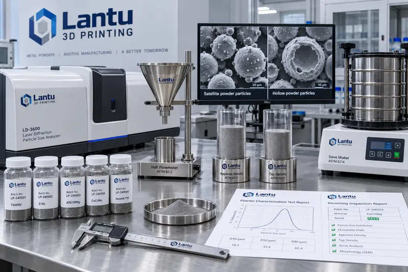
Laser diffraction particle size analyzers provide a volume-weighted distribution. At least four values should be reviewed in the report: D10, D50, D90, and span (D90-D10)/D50. A typical LPBF range is D10 ≈ 15–20 μm, D50 ≈ 30–40 μm, and D90 ≈ 55–65 μm, with span controlled between 1.2 and 1.8.
The two tails are the real concern. An excessively low D10 value (too many fines) has three consequences: increased surface area raises oxygen adsorption, reduced powder flowability leads to uneven layer thickness, and laser scanning generates substantially more spatter and fumes, potentially shortening protective-lens replacement intervals from 400 hours to 250 hours. An excessively high D90 value (too many coarse particles) can cause drag marks beneath the recoater blade, while coarse particles can also create localized lack-of-fusion defects.
A practical criterion is as follows: if D10 for a single batch is below 12 μm or D90 exceeds 70 μm, the batch should be classified as requiring disposition even if D50 remains within specification. Recycled powder requires particular attention to particle-size drift: sieving removes coarse particles, but fines accumulate with repeated reuse. Therefore, powder recycled more than five times typically has a D10 value 3–6 μm lower than virgin powder.
2. Apparent Density and Tap Density: Primary Indicators of the Powder Bed
Apparent density is the density of freely packed powder. For Ti6Al4V, it is typically 2.3–2.6 g/cm³, approximately 52–58% of theoretical density. Tap density is measured after a specified number of taps and is generally 2.8–3.1 g/cm³. Their ratio is called the Hausner ratio, one of the lowest-cost indicators for evaluating flowability:
Hausner ratio < 1.25 → good flowability; suitable for direct use; 1.25–1.40 → moderate flowability; recoating speed should be reduced or the number of blade compaction passes increased; > 1.40 → poor flowability and nonuniform powder-bed density; not recommended for thin-layer processes (20–30 μm).
Apparent density directly determines the actual powder mass in each layer. Consider a machine with a 30 μm layer thickness and a 250 × 250 mm build area: if apparent density decreases from 2.5 to 2.2 g/cm³, powder mass per layer declines by approximately 12%. With unchanged laser energy input, this is equivalent to a 12% increase in energy density—one reason why the same parameter set may perform normally with virgin powder but produce keyholing with recycled powder. Therefore, energy density must be rechecked when changing batches or powder types, rather than simply reusing the previous batch's process card.
3. Hall Flow Rate: Turning Flowability into a Pass/Fail Number
The Hall flowmeter measures the time required for 50 g of powder to pass through a standard funnel with a 2.54 mm orifice, expressed in s/50 g. This is the standard method specified in ASTM B213 and one of the easiest requirements to include on an incoming inspection form.
Reference ranges are as follows: spherical gas-atomized powders such as Ti6Al4V and 316L generally flow at 15–25 s/50 g; 316L is somewhat faster at 13–20 s/50 g; and AlSi10Mg typically ranges from 25–40 s/50 g due to its low density and tendency to bridge. Any result exceeding 45 s/50 g, or interrupted flow caused by bridging or intermittency, should be rejected outright. Such powders can produce periodic powder starvation beneath the recoater blade.
Two measurement pitfalls require attention. First, the powder must be dry: when moisture exceeds 0.05% by mass, liquid bridges between particles can worsen Hall flow by 20–40%. Before testing, powder should therefore be vacuum dried at 80–120°C for 2–4 hours, cooled to room temperature in a desiccator, and tested immediately. Second, recycled powder must be sieved first; otherwise, residual agglomerates and spatter particles can block the funnel outlet, causing the test to measure blockage time rather than flow time.
4. Satellite and Hollow Particles: Quantifying Morphological Defects
During gas atomization, small droplets can adhere to the surfaces of already-solidified larger particles, forming satellite particles. Their impact is twofold: they increase mechanical interlocking between particles and reduce flowability; during recoating, these protrusions hinder particle rearrangement and lower powder-bed density. Hollow particles are closed-pore particles created when atomization gas becomes entrapped inside molten droplets. They may show no abnormality during recoating, but can rupture in the melt pool and release gas, creating spherical pores—defects often incorrectly attributed to process parameters.
Two approaches with different cost levels are available for quantification. Low-cost approach: after metallographic sample preparation, randomly capture 10 fields of view at 500× magnification, count at least 200 particles per field, and calculate the proportions of satellite particles (particles with separate attached spheres on their surface) and hollow particles (particles with enclosed pores visible in cross-section). Recommended acceptance thresholds are satellite particles ≤ 8% and hollow particles ≤ 1.5%. High-resolution approach: use SEM with automated image analysis to generate both sphericity (circularity) distributions and combined particle-size/morphology distributions. Measurement time is approximately 20–30 minutes per sample, making this approach suitable for first-batch qualification of new suppliers.
Hollow particles also have an indirect indicator: apparent density significantly below the historical value for the same batch category while particle size distribution remains unchanged. For example, one batch of 316L showed an apparent density of 4.0 g/cm³ versus a historical average of 4.4 g/cm³, while D50 and span remained normal. Retesting found a hollow-particle proportion of 3.8%. Hollow particles had reduced packing density, making this the most economical early-warning signal.
5. The Coupling of Surface Area and Oxygen Pickup
BET specific surface area is a sensitive indicator of fine-particle content. For spherical Ti6Al4V with D50 = 35 μm, the theoretical geometric specific surface area is approximately 0.02 m²/g. If measured BET values reach 0.05–0.08 m²/g, this indicates a substantial amount of fines, rough particle surfaces, or satellite structures. For the same exposure conditions, doubling specific surface area approximately doubles the oxygen uptake rate. This is why batches with a high fines fraction experience more rapid oxygen increases after opening.
Incoming inspection should establish a coupled criterion: when BET specific surface area exceeds the historical average by 30%, the post-opening usage window should be reduced from the standard 30 days to 14 days even if oxygen content remains compliant, and an additional drying step should be added before machine use.
6. An Actionable Incoming Inspection Checklist
Organizing these indicators into a pass/fail inspection form is far more effective than discussing whether “sphericity is good.” Six mandatory tests and two spot-check tests are recommended for each batch:
Mandatory tests: ① particle size distribution, including D10/D50/D90 and span; ② apparent density and tap density, with Hausner ratio calculation; ③ Hall flow rate (s/50 g, average of three repetitions); ④ oxygen and nitrogen content (inert gas fusion with infrared/thermal conductivity detection); ⑤ moisture content (Karl Fischer titration or loss on drying); ⑥ appearance and foreign matter inspection (white-cloth wipe test and magnetic separation check).
Spot-check tests, triggered for the first batch from a new supplier or when process anomalies occur: ⑦ metallographic/SEM determination of satellite and hollow particle proportions; ⑧ BET specific surface area.
Acceptance rules must be written as numerical thresholds rather than descriptive terms, and each item must specify the test method standard and equipment. Otherwise, suppliers and buyers will use different methods and their data will never align. Retained samples are equally critical: keep a sealed 200–300 g sample from each batch, labeled with the batch number, delivery date, and test report number. Retain it until the batch is consumed, then keep it for an additional six months. If batch-level defects arise, this is the only traceable evidence.
Conclusion
The core of powder acceptance is not measuring more indicators, but measuring the physical quantities that affect recoating and melting, and defining them as pass/fail thresholds. For particle size distribution, examine the D10 and D90 tails rather than D50 alone; use apparent and tap density to calculate the Hausner ratio and determine whether energy density requires recalibration; use Hall flow rate as a hard flowability criterion; and quantify satellite and hollow particles by metallography or SEM, with anomalous apparent density serving as a low-cost warning signal for hollow particles.
Within Bluprint 3D's delivery system, powder characterization is not merely an incoming-inspection procedure but a prerequisite for the process window—only when powder behavior is measurable can printing parameters be reproducible and delivery quality be assured.
Invia un modello, un disegno, un'immagine o note scritte. Gli ingegneri valuteranno materiale, processo, finitura e consegna in base all'uso effettivo.