
Introduction: The Engineering Variable Reduced to “Antistatic Clothing”
In the work instructions of most 3D printing workshops, static electricity appears only twice: “wear antistatic clothing” in occupational health training, and “dry sweeping is prohibited” in dust-cleaning procedures. Yet the issues that are genuinely difficult to resolve on the shop floor come neither from people nor from brooms: the same lot of Ti6Al4V powder shows weighing drift of 0.3% to 0.8% after sieving; reclaimed powder forms a ring on the inner wall of transfer containers; intermittent thin powder bands appear ahead of the recoater during spreading; and resin parts attract another layer of fine dust after cleaning. The common upstream cause is charge accumulation during sieving, pneumatic conveying, pouring, and wiping. However, workshops often have no measurable value, no decision threshold, and no record traceable to a build ID. lantu3D manages the journey from drawing to physical delivery as a lifecycle chain. Electrostatic condition is a process variable that has long been missing from that chain: it is neither a PPE checklist item nor an accessory to temperature and humidity records, but a process state requiring independent definition, measurement, and release.
I. Define the Boundaries First: Protecting People, Parts, and What This Layer Controls
The most common mistake is to classify static electricity directly as part of EHS dust-explosion control. The three areas are adjacent, but their subjects are fundamentally different. The EHS layer asks, “Will operators inhale metal powder, suffer laser burns, or face a dust-cloud ignition event?” Its outputs are PPE lists, interlocks, and emergency response cards. The workshop environmental-control layer asks, “At 45% ±5% relative humidity, will powder absorb moisture and subsequently vaporize in the melt pool to form porosity?” Its outputs are continuous temperature/humidity records and moisture-content gates. This layer asks whether charges accumulated between powder and containers, screens, piping, and workbenches have been dissipated, and on what basis a container of powder may be loaded into a machine. In short: if it can be expressed as “a measured grounding resistance, a surface-resistance classification table, a charge-decay curve, or a shift-by-shift inspection log,” it belongs to the electrostatic engineering layer. Its purpose also differs from humidity control under 8582: the humidity upper limit there prevents moisture absorption, while the humidity lower limit here provides a path for charge dissipation. The two windows must overlap rather than replace each other.
II. Four Categories of Measurement Points and Decision Thresholds
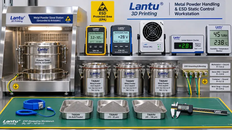
The first category is the dissipation path. Equipment protective earth, sieving stations, transfer carts, powder containers, and bench mats must be equipotentially bonded. The connection resistance from the common grounding point to each endpoint should be ≤1 Ω, while resistance to ground for antistatic work surfaces should remain in the dissipative range of 10⁵–10⁹ Ω. Below 10⁵ Ω, personnel shock risk and current limiting must be assessed; above 10⁹ Ω, dissipation is too slow and the surface effectively behaves as an insulator. The classification principles of IEC 61340-5-1 and ANSI/ESD S20.20 may be used as references. It is not necessary to replicate the entire system, but the workshop must define in its own work card which points to test, which meter to use, how often to test, and what to do when limits are exceeded. The second category is workstation electrostatic potential, measured using a non-contact electrostatic field meter at four locations: the pouring point, above the screen, the weighing bench, and inside the recoater-chamber door. A limit of ≤±100 V is recommended around sensitive electronic scales and sensors, and ≤±500 V for general workstations. Readings must be taken while equipment is operating; a zero reading when stopped is meaningless. The third category is charge decay. For samples of bench mats, containers, and filter media, the time required to decay from ±1000 V to ±100 V should be ≤2 s, or the half-life should be recorded and a baseline established. Newly replaced plastic liners, new lots of filter bags, and freshly cleaned containers must be retested. The fourth category is environmental neutralization. Relative humidity should remain above 40% RH and overlap with the 45% ±5% window for build stability; the combined operating window should be 45%–50%. Ionizing blowers should be used only where insulating parts are unavoidable, with balance voltage ≤±35 V and decay time ≤2 s, and they must be included in routine inspection rather than installed and forgotten.
III. Four Pathways Through Which Static Electricity Affects Build Quality
Pathway one: sieving and screen blinding. Charged fine powder adheres to screen wires, reducing effective open area. Oversize material may then be misclassified as “agglomerated powder,” causing available reclaimed-powder quantity to be underestimated. Pathway two: weighing and blending. Powder charge varies with ambient humidity and conveying speed, producing irregular electronic-scale drift of 0.3%–0.8%. Blend ratios and net material consumption per part are distorted, contaminating activity data used in cost sheets and carbon accounting. Pathway three: recoating and powder layers. Charged powder adheres to the recoater edge and forms thin powder bands at substrate edges, creating local powder-layer thickness variation. Subsequent balling and lack-of-fusion issues may then be incorrectly attributed to laser parameters. Pathway four: surfaces and cleanliness. Resin parts and cleaned metal parts exhibit increased dust attraction, internal-channel cleanliness reinspection fails, and adhesion before blasting or coating becomes unstable. These four pathways share a common feature: the symptoms appear to belong to sieving, metrology, build, and post-processing respectively, while the root cause lies in one shared location. Without electrostatic records spanning process steps, the shop can only keep adjusting parameters one stage at a time.
IV. Engineering Controls: Dissipation First, Neutralization as Backup
The control sequence must not be reversed. First establish conductive paths: bond metal containers, sieving machines, transfer carts, and piping flanges, and connect them to a single grounding point. Do not use “application of antistatic agent” as a substitute for bonding conductors. Select dissipative materials for benches and floors and include them in the classification table. Insulating plastic trays may be used only for short-term transfer and must be paired with ionization. Next, classify container and tooling materials: classify containers, liners, scoops, and screen frames as conductive, dissipative, or insulating based on surface resistance. Insulating items must not directly contact powder intended for machine loading. For every new purchased item, sample-test surface resistance upon receipt and retain samples. Third, interlock humidity with process operations: when humidity falls below 40% RH, suspend sieving and pouring. Work may resume only after humidity returns to the combined window and electrostatic potential is retested; event timestamps must be linked to the shift work order and build ID. Only then should active neutralization devices such as ionizing blowers and static-elimination bars be used, and only at stations where materials cannot be changed. It must be emphasized that blowing powder with compressed air is both a dust-explosion hazard and a highly charge-generating process; it must never be used for powder cleaning.
V. Shift-by-Shift Inspection Logs and A/B/C Three-State Release
A six-field inspection card is recommended: measured shift humidity and data-logger ID; maximum electrostatic-potential values at four workstations; sampled equipotential-bonding test points and values; ionizer balance voltage; powder lot numbers and build IDs involved in sieving, pouring, and weighing during the shift; and the inspector and verifier. Results are classified into three states. State A means all six items are within limits and machine loading is permitted. State B means one item is slightly out of tolerance, such as potential between ±500 V and ±1000 V or decay time of 2–4 s. Release is permitted only after increased-frequency retesting and first-article standard-sample confirmation, and the lot must be separately identified. State C applies to an open grounding circuit, humidity below 40% RH, potential exceeding ±1000 V, or decay time above 4 s. Machine loading is immediately frozen, and powder-layer images, weighing records, and witness-coupon results for all builds recoated since the last acceptable checkpoint must be reviewed. No concession release is permitted without acceptable evidence. Recovery requires retesting grounding and potential, repeating the first-article check, and joint signoff by process engineering and quality; simply adding a record after the fact is not sufficient to restart production. Logs should be retained with dual indexing by lot number and equipment ID, allowing any delivered part to be traced back to the electrostatic condition of its production shift. Together with inspection lots, heat-certification chains, and measurement traceability, this forms the delivery evidence package rather than a separate system.
VI. Thirty-Day Deployment and Common Misconceptions
Week one: establish a baseline. Measure all four categories of points across the workshop, map high-charge stations, and prioritize pouring points and sieving stations. Week two: standardize hardware. Add bonding conductors, replace benches and containers with dissipative versions, equip insulating stations with ionizers, and verify balance voltage. Week three: issue work cards and train personnel. Post inspection cards, classification tables, A/B/C criteria, and recovery procedures; have operations and quality each practice retesting and joint signoff. Week four: perform a traceability drill. Randomly select a delivered part and require the team to retrieve the shift electrostatic inspection record, powder lot number, build layer number, and first-article confirmation record within 30 minutes. The target first-pass retrieval rate is ≥95%. Four common misconceptions are: treating the distribution of antistatic clothing as completed static control; setting only an upper humidity limit to prevent moisture absorption while omitting a lower limit to prevent charge accumulation; testing only equipment protective earth but not the powder-contact endpoints such as containers and bench mats; and failing to retest surface resistance and decay time after changing screens, liners, or cleaning agents. All of these can be blocked through mandatory fields on the inspection card.
Conclusion
In 3D printing workshops, static electricity has long been a variable that “everyone mentions, but no one assigns a value.” Separating it from PPE lists and temperature/humidity records, defining it through five measurable groups—dissipation paths, surface resistance, electrostatic potential, charge decay, and minimum humidity—and linking the results to work orders, powder lots, and build IDs as release criteria completes the chain from design to physical delivery. For lantu3D, the value is not in adding several record sheets. It is in enabling engineers to rule out a verifiable common root cause first when screen blinding, weighing drift, intermittent powder layers, or surface dust attraction recur, rather than repeatedly adjusting parameters across four separate process stages.
Invia un modello, un disegno, un'immagine o note scritte. Gli ingegneri valuteranno materiale, processo, finitura e consegna in base all'uso effettivo.