
Introduction: One Alarm, Three Shifts, Three Responses
A metal powder bed fusion machine repeatedly displays a “high oxygen content” alert during the night shift: one team continues printing based on experience, another stops the machine and re-purges the chamber, and a third simply resets the alarm. All three records describe the same condition, yet none can answer: “Which event code does this alert correspond to? What is the trigger threshold? Is printing allowed to continue? Is re-verification required after reset?” When supporting lifecycle projects from design blueprints to physical delivery, lantu3D has found that production floors often lack neither sensors nor inspection checklists. What they lack is a controlled code table that translates raw events output by equipment controllers into actionable determinations. This article is not about how to repair equipment, but rather the upstream layer: how alarms and event codes are numbered, classified, linked to interlock actions, controlled for suppression and reset, and frozen with firmware versions, so that the same event receives the same response on every shift.
1. Define the Boundary First: Alarm Codes, Fault Symptoms, and Quality Events Are Not One Table
First, distinguish three objects that are easily conflated. An alarm code is a structured identifier output bitwise or by word from the equipment control system; its meaning is defined by the code table and must be unique, stable, and machine-readable. A fault symptom is an operator-visible description, such as “streaks in powder spreading”; it is natural language, and multiple symptoms may point to the same code. A quality event is a subsequent determination of part impact, such as “this build is quarantined pending inspection,” and belongs to the release-decision layer. Previously discussed three-tier power-quality measurement points and waveform records, predictive-maintenance mappings of failure modes to monitoring indicators and thresholds, and equipment inspection states of normal/abnormal/reinspection all consume certain events to make another decision. They do not define “where a code originates, how code domains are divided, or what happens to historical records when a code changes.” The key classification question at this layer is: Does the article address “how to calculate a conclusion after receiving a signal,” or “what that signal is called at the moment it is generated, what level it belongs to, and what actions it may trigger”? Only content that can be reduced to “one code, one classification table, one interlock rule, and one version-freeze record” belongs to the code-table engineering layer.
2. Code Domains: Give Every Event a Permanent, Non-Reusable Identity
A five-segment fixed-length code is recommended: E-<equipment family, 2 digits>-<subsystem, 2 digits>-<sequence number, 3 digits>-<severity, 1 digit>. For example, LP-GS-0217-3 represents event No. 217 for the powder-spreading/gas-system domain, with severity level 3. Equipment families are categorized by process platform (LP for laser powder bed fusion, BJ for binder jetting, PJ for photopolymerization, and DE for directed energy deposition). Subsystems are categorized by functional domain (GS for gas flow and oxygen content, RC for recoating and blade systems, LS for lasers and optics, TH for build-plate preheating, MT for motion and servo systems, PW for power supply and utilities, and CT for control and communications). For each code, the code table should at minimum freeze eight fields: unique code, standard Chinese and English descriptions, trigger-condition expression, default severity, default interlock action, permitted operating states, firmware version first taking effect, and responsible response role. Once assigned, a sequence number must never be reused. Retired events should only be marked deprecated while retaining historical mappings. Old numbers must never be assigned new meanings; otherwise, a quality record from three years earlier could be interpreted as an entirely different event during retrospective review.
3. Classification and Interlocks: A Four-State Action Matrix from “Notification” to “Safety Shutdown”
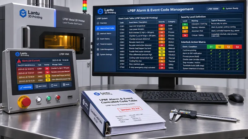
Four severity levels are recommended, with each level tied to one default action to eliminate discretionary on-site decisions: S1 notification (event log only, with no interruption to the build; for example, a filter differential-pressure reminder approaching replacement); S2 warning (continue building but reduce speed or apply a mark; for example, when chamber oxygen reaches the 800–1000 ppm range, automatically extend interlayer purging and mark the affected layer); S3 process hold (pause recoating while maintaining the current layer number and inert atmosphere; for example, oxygen content >1000 ppm for ≥2 s, or measured laser power deviating from setpoint by ±8% for more than three layers). Before resuming the build, fusion quality must be reviewed for the three layers above and below the event layer. S4 safety shutdown (cut off laser output while maintaining gas circulation, with the build immediately quarantined; for example, protective-gas interruption, chamber-door interlock activation, or emergency-stop circuit actuation). S4 events must never be automatically reset or suppressed. The action matrix should specify six columns: “severity → interruption required → atmosphere retained → build quarantined → first-article re-verification required → notification role.” It should be issued after joint approval by process, equipment, and quality functions.
4. Debouncing, Trigger Conditions, and Evidence Snapshots: Make Every Event Reproducible
A trigger condition cannot simply state “oxygen content high”; it must be expressed in a reproducible format: measured variable / comparison operator / threshold / duration / hysteresis band / enabled operating state. For example, oxygen content may use a 1000 ppm threshold, a 2 s duration, and a 5% hysteresis band, clearing only after falling below 950 ppm. It is enabled only during build and preheat states, and is not evaluated during standby or maintenance. Laser-power deviation may use ±8% over three consecutive layers, debounced at a 100 ms sampling cycle and confirmed only after three consecutive qualifying cycles; transient spikes of <50 ms are recorded as transients and do not escalate severity. Each confirmed event should generate an evidence snapshot with ten fixed fields: event code, timestamp (synchronized with the equipment clock, drift ≤1 s), current layer number, actual laser power, recoater-axis position, oxygen content and dew point, parameter-package hash, code-table version, firmware version, and operator ID. Key-variable waveforms from 200 ms before to 1 s after the event should also be retained. Without this snapshot, the impact boundary cannot be determined afterward, and S3/S4 release decisions have no supporting basis.
5. Suppression, Reset, and Temporary Bypass: Put Exceptions Inside an Authorization Cage
Legitimate suppression needs do exist on the shop floor, such as during oxygen-analyzer calibration, but they must be controlled through engineering constraints: suppression is permitted only for S1–S3, while S4 is permanently prohibited; the request must state the code number, reason, alternative monitoring method, and validity period; the validity period should be ≤8 hours or ≤1 build, whichever occurs first, and must expire automatically; execution requires dual authorization by equipment and quality personnel. During suppression, all events must still be recorded normally; they are only tagged with suppressed=true and the authorization request number, and must never be silently discarded. Reset is likewise not merely pressing a button: before resetting an S3/S4 event, the responsible person must enter a root-cause code corresponding to a fault-dictionary entry. After reset, a standard first-article specimen must be verified, and the three layers above and below the event layer must be reviewed for lack of fusion and porosity. Build quarantine may be lifted only when all four records are complete. It is recommended to include “suppression rate ≤1% of builds,” “uncategorized-event ratio ≤2%,” “more than five repeats of the same root cause within one hour automatically generates a root-cause work order,” and “event-to-snapshot completeness ≥99%” in the monthly dashboard.
6. Version Freezing and Change Control: Where Do Old Codes Go After a Firmware Upgrade?
A code table is a controlled document, not an Excel file to be edited casually. Each release should generate a version number, SHA-256 hash, effective date, applicable equipment serial-number list, and minimum firmware version. These should be written into the delivery evidence chain through a three-key association with the parameter-package version and build number. Adding or revising a code must follow a change request: impact analysis (which historical records, work instructions, and interlock logic are affected) → cross-functional review → old-to-new code mapping → cutover on the effective date → retirement of old work instructions. Before and after a firmware upgrade, a code-table consistency comparison must be performed: verify item by item that the code number, severity, and description actually output by the controller match the current controlled version. If they do not match, machine-release authorization must be frozen. Historical code tables and event logs should be retained for no less than the product lifetime plus three years and archived in read-only form.
7. Implementation Checklist and Common Pitfalls
Implementation can be advanced over 30 days: in Week 1, export the complete controller event list, renumber it using the five-segment format, and establish a code-domain register; in Week 2, complete the four-level action matrix and trigger-condition expressions, adding debounce and hysteresis bands; in Week 3, connect the ten event-snapshot fields automatically with parameter-package hashes and layer numbers; in Week 4, conduct a 30-minute retrospective drill—randomly select an S3 event from three months earlier and require reconstruction of the applicable code-table version, trigger condition, snapshot, and release conclusion, with a target reconstruction success rate of ≥95%. Four common pitfalls are: writing alarm codes as natural-language descriptions, making them unreadable by machines; defining only thresholds without duration and enabled operating states, causing maintenance-state false-alarm floods; failing to record events during suppression, breaking the evidence chain afterward; and continuing to use an old code table after firmware upgrades, causing old and new meanings to be confused.
Conclusion
The controlled definition of equipment alarms and event codes is the foundational engineering layer that translates “what the machine says” into “what the shop floor must do.” It does not replace energy-consumption accounting, power-quality management, predictive maintenance, or inspection-lot management; rather, it provides these methods with a stable, reproducible, and traceable input dictionary. For platforms spanning the full chain from design and process development through manufacturing and physical delivery, only by making every code unique, every severity action unique, every exception traceable, and every version freezable can a night-shift alert become an engineering fact that produces the same conclusion on every shift.
Invia un modello, un disegno, un'immagine o note scritte. Gli ingegneri valuteranno materiale, processo, finitura e consegna in base all'uso effettivo.