
Introduction: Why the Same CMM Passes in the Morning but Fails on an Afternoon Retest
Across the 3D-printing delivery chain, dimensional disputes often arise not because the part changed, but because the measurement environment changed. A coordinate measuring machine (CMM) may measure an assembly-surface flatness of 0.06 mm in the morning, then produce 0.11 mm when the same part is retested in the same fixture orientation that afternoon. A roughness tester may measure the same polished reference coupon five consecutive times, with Ra readings fluctuating between 1.6 μm and 2.4 μm. If the issue is attributed only to gauge drift or operator performance, process capability can easily be misjudged. For additive parts such as conformal-cooling inserts, lattice thin-wall components, and porous metal sealing surfaces, measuring forces are low, sampling density is high, and feature scales commonly fall between a few and several tens of micrometres. Environmental micro-vibration can therefore be directly superimposed on raw point clouds and profile traces.
lantu3D views the path from digital design to physical delivery as a verifiable lifecycle chain, with inspection data serving as release evidence along that chain. This article does not address equipment selection or calibration intervals. Instead, it examines what justifies signing a measurement report based on the vibration condition of the floor and table at the exact moment precision inspection takes place: treating micro-vibration as a measurable process state and defining measurement locations, thresholds, per-shift checks, data tagging, and retest triggers.
1. First Distinguish Three Layers: Equipment Foundations, Build Environment, and Inspection Micro-Vibration
In existing engineering articles, “vibration” commonly appears under three different subjects and must be separated. The first layer is equipment installation and site acceptance testing (SAT): 10033 requires confirmation of foundation load capacity and site conditions before delivery to avoid accuracy drift after production starts; the annual calibration procedure in 10382 includes foundation settlement and changes in nearby vibration sources in report remarks as potential error sources. The second layer is workshop environmental control (8582): temperature, humidity, cleanliness, and powder moisture absorption affect melt-pool stability and protect the built part. The third layer—the subject of this article—is the micro-vibration condition of the metrology room or precision inspection area, which protects the validity of measurement data used for conformity decisions.
All three may use terms such as “foundation,” “vibration,” and “environment,” but their decision objects differ. SAT answers whether equipment can enter production; calibration answers whether machine axes are accurate; environmental control answers whether powder will absorb moisture; micro-vibration control answers whether a given CMM point cloud, roughness profile, or set of industrial CT reconstruction slices has been contaminated by environmental noise. Treating the third layer as a subordinate note to the first two leaves a missing link in release criteria.
2. Four Pathways Through Which Micro-Vibration Affects Additive-Part Measurement
The first is contact profilometry. A stylus roughness tester scans surfaces with a 2–5 μm tip radius. Unpolished LPBF side surfaces commonly have Ra values of 8–20 μm, while partially melted particles and layer-valley bottoms are inherently steep. Low-frequency table motion at 0.1–0.5 Hz or typical factory disturbances at 20–80 Hz can be recorded as profile fluctuations, systematically increasing Ra and Rz. The second is CMM point-cloud measurement. Air-bearing guideways are sensitive to sustained micro-vibration. In scanning mode, relative motion between probe and workpiece changes trigger-point coordinates, particularly affecting thin-wall parts with flatness criteria at the 0.05 mm level. The third is optical and CT inspection. White-light interferometry and confocal microscopy reconstruct surface topography with submicron vertical resolution, and vibration during exposure or scanning can cause fringe misalignment. Industrial CT reconstruction slices can develop edge artifacts from slight sample-stage motion, which may be misread as lack of fusion or porosity. The fourth involves fine readings from balances, hardness testers, and furnace witness specimens, where micro-vibration undermines repeatability of 0.1 mg weighing and indentation-diagonal measurements.
A practical criterion is to measure the same reference artifact 10 times during a quiet window and 10 times during a disturbance window. If the difference in mean is less than 10% of the maximum permissible error and the standard-deviation ratio does not exceed 1.3, the inspection item may be considered insensitive to current vibration conditions. Once the standard-deviation ratio exceeds 1.5 or mean shift exceeds 10%, vibration status must be defined as a controlled condition of the measurement method rather than simply retesting and averaging the results.
3. Four Types of Measurement Points and Determinable Thresholds
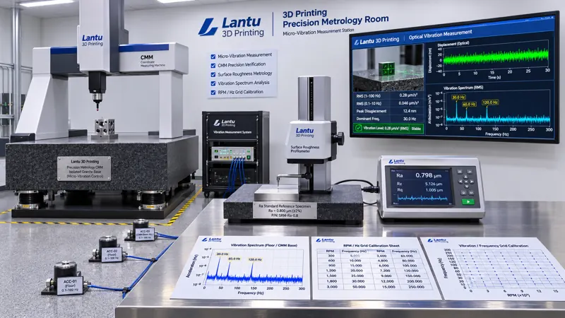
A four-layer measurement layout—“source, transmission, table, instrument”—is recommended, with all points linked to the inspection-area ID and timestamp. First, floor vibration: install low-frequency accelerometers at the four corners of the metrology room and near the CMM base. Sample at ≥200 Hz and record RMS velocity (mm/s) and dominant frequency over the 1–80 Hz range. For general precision inspection areas, a VC (Vibration Criterion) target of VC-C or better is recommended, corresponding to RMS velocity controlled within 50 μm/s. Perform an additional measurement at night or during equipment shutdown as a baseline reference. Second, the isolation table: measure transmissibility between table and floor, T=a_table/a_floor. In the 1–10 Hz band, T≤0.3 is acceptable, 0.3–0.6 requires observation, and >0.6 or the presence of a resonance peak requires the station to be taken out of service. Third, the instrument itself: record CMM air-bearing pressure, roughness-tester stylus force, and CT sample-stage repeatability according to manufacturer inspection requirements. When vibration is abnormal, first rule out air-bearing and fastening issues. Fourth, associated environmental parameters: temperature of 20±1 °C, humidity of 45%±10% RH, differential pressure, and events such as personnel movement or forklift traffic. Use door sensors or a simple event button for timestamped tagging so abnormal readings can later be correlated.
Thresholds should not simply be made as strict as possible. They should be classified by inspection item. Category A, including CTQ dimensions, sealing-surface flatness, and surface topography with Sa≤1 μm, requires floor RMS≤25 μm/s, table T≤0.2, and no personnel-movement event within one minute. Category B, including general Ra and external dimensions, may allow RMS≤50 μm/s and T≤0.3. Category C, including visual inspection and coarse positioning, requires records only and no interlock. Thresholds for each category should be included in the applicable inspection work instruction rather than displayed as generic wall slogans.
4. Per-Shift Inspection Logs and A/B/C Three-State Release
Implement micro-vibration control through a six-field log: inspection-area ID; measurement-point ID and calibration validity; actual shift RMS/T values; dominant frequency and spectrum screenshot filename; associated events such as material handling, HVAC start/stop, or adjacent-equipment machining; and decision status and signature. Before startup, conduct a 10-repeat repeatability check using a reference artifact and record the standard deviation. If deviation from the baseline of the previous accepted shift exceeds 20%, suspend report issuance first.
The system has three states. State A (release): all four measurement layers are within applicable category thresholds, reference-artifact repeatability passes, and no associated events occurred. Reports may be issued normally, with the vibration-status batch number automatically included in measurement records. State B (restricted use and retest): RMS or T slightly exceeds the limit but remains below 1.5 times the threshold, with no resonance peak. Only Category B/C inspections are permitted. Category A items must be retested during a quiet window; both sets of raw data for the same part must be retained and must not overwrite each other. The report shall state the reason for retesting and both results. State C (freeze): floor RMS exceeds twice the category threshold, a resonance peak occurs on the table, an air-bearing abnormality is present, or the reference-artifact standard-deviation ratio exceeds 1.5. Immediately stop issuing reports and freeze all Category A data generated at that station since the last accepted checkpoint. Review raw point clouds, profile traces, and CT slices; where necessary, retest retained samples. No concessionary release is permitted without conforming evidence.
5. Interfaces with Existing Quality Systems Rather Than Creating Another One
The micro-vibration log is not a second quality system. It adds a field to the existing evidence chain: whether the environment was controlled when measurement occurred. It interfaces with the gauge register and GR&R in 8499: reference-artifact data from intermediate checks must include the vibration-status batch number; otherwise, gauge drift cannot be separated from environmental disturbance. It interfaces with inspection batches and raw records in 11305: ALCOA+ requires records to be contemporaneous, original, and attributable, so vibration spectrum screenshots and event timestamps should also be retained as raw records with an audit trail for changes. It interfaces with outsourced testing in 12084: where an external laboratory report is used for Category A criteria, the purchase order should require the laboratory to provide the environmental vibration classification during testing or at minimum declare compliance with the environmental conditions of the method standard. It interfaces with equipment calibration in 10382: “changes in nearby vibration sources” in annual calibration reports should be upgraded from a remark to a recalculable measurement-point value, with floor RMS measured and archived before and after calibration.
A 30-day implementation sequence is recommended. In Week 1, select the inspection area, install measurement points, and establish a seven-day baseline while identifying frequency signatures from forklift routes and air-compressor cycling. In Week 2, incorporate thresholds by A/B/C category into three work instructions and improve station isolation and walking routes. In Week 3, connect the six-field log to work orders and report templates, and conduct a disturbance drill by deliberately starting an air compressor at an adjacent station. In Week 4, conduct a 30-minute traceability drill: randomly select one released report and trace from the report number back to the shift RMS, spectrum screenshot, reference-artifact repeatability, and signatory. The target completeness rate is ≥95%.
6. Common Failure Modes and Checklist
Five common pitfalls are: purchasing an isolation table without measuring transmissibility, allowing a resonance peak to fall within the normal operating frequency range; treating an SAT foundation-acceptance report as permanent proof of environmental suitability while ignoring new vibration sources after production-layout changes; recording only temperature and humidity but not personnel or forklift events, making abnormal readings impossible to attribute; using “retest and average” to conceal contaminated data, violating raw-record principles; and applying one plant-wide micro-vibration threshold, making Category A too loose and Category C too strict, increasing cost while failing to control disputes. The checklist can be condensed into seven questions: Are measurement points within calibration validity? Does the frequency range cover 1–80 Hz? Has table transmissibility T been measured? Has the 10-repeat reference-artifact test been completed? Are associated events timestamped? Can the report be traced back to a vibration-status batch number? Does the State C freeze scope begin from the previous accepted checkpoint?
Conclusion
As dimensional and surface requirements for additive parts become increasingly refined, small disturbances in the measurement environment can no longer remain in “remarks.” By separating micro-vibration in precision inspection areas into four measurable categories—floor RMS, table transmissibility, instrument condition, and associated events—setting A/B/C thresholds by inspection item, linking every report to the environmental state at the time of measurement through per-shift logs, and freezing and reviewing data after exceedances rather than averaging them away through retesting, CMM point clouds, roughness profiles, and CT slices can become genuinely reproducible, reusable, and verifiable release evidence. For lantu3D, this does not merely add another piece of equipment; it completes the controlled condition at “the moment of measurement” within the evidence chain from digital model to physical delivery.
Invia un modello, un disegno, un'immagine o note scritte. Gli ingegneri valuteranno materiale, processo, finitura e consegna in base all'uso effettivo.