Introduction: Washed Does Not Mean Clean—Pre-Delivery Cleanliness Must Be Determinable
After support removal, blasting, ultrasonic cleaning, and drying, metal LPBF parts may appear clean. However, internal channels, lattice porosity, and support-contact surfaces can still retain metal powder, detergent surfactants, salt ions, and machining-fluid films. Such residues may not immediately affect dimensional inspection reports, but can later cause coating blistering, poor adhesion, microleaks at sealing surfaces, and in-service corrosion during anodizing, electroplating, bonding, brazing, or assembly. For example, in a Ti6Al4V hydraulic valve block with conformal internal channels, if chloride-ion concentration remains high in the channels after cleaning, pitting after 96 hours of salt-spray exposure will often first occur at channel bends rather than on external surfaces. The problem is that most shop-floor cleaning processes specify only operational actions—such as cleaning duration and the number of water changes—without providing evidence for why a part is considered clean or whether it can be signed off for the next process. lantu3D regards the journey from design blueprint to physical delivery as lifecycle management: cleanliness is not an action, but a verifiable release status.
1. Define Residues as Measurable Objects, Not Descriptive Terms
The first step toward a determinable release is to break down “clean” into four measurable residue categories and their migration paths. First, particulate residues originate from uncleared powder and blasting media, creating risks of channel blockage and mating-surface scratches. Second, ionic residues originate from cleaning agents, tap water, and fingerprints; key species include Cl⁻, Na⁺, and SO₄²⁻, with electrochemical corrosion as the primary risk. Third, organic residues originate from cutting fluids, release agents, and ultrasonic cleaning solutions, reducing coating adhesion and bond strength. Fourth, non-volatile residue (NVR) is the total dried mass of the above materials. Each category must have a defined sampling method, detection limit, and acceptance criterion; visual confirmation of “no visible contamination” cannot substitute for these controls. In engineering practice, parts should first be divided into three cleanliness grades according to use: general structural parts (G1), functional parts with coatings or bonded joints (G2), and pressure-bearing or implant-related parts with internal channels (G3). Higher grades require more sampling locations and acceptance criteria, avoiding excessive, one-size-fits-all testing for every part.
2. Freeze Sampling Methods First: Extraction, Flushing, Wiping, and the Three-Control Set
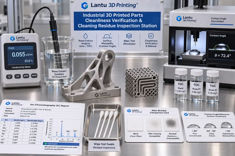
Reliable acceptance criteria depend on controlled sampling methods. Four common approaches are used: full-part extraction, in which a part is immersed in a measured volume of deionized water and the extract is tested after ultrasonic treatment or agitation for a specified duration; internal-channel flushing, in which channels are flushed with a measured volume of deionized water at a fixed flow rate and the effluent is collected; surface wiping, in which a pre-wetted lint-free wipe is used over a specified 100 cm² area and then extracted; and mass difference after drying. Every sampling event must include a three-control set: a blank control using the same batch of deionized water, the same container, and the same procedure without a part; a spike control containing a known quantity of reference material added to the blank to calculate recovery; and a duplicate sample from two adjacent areas of the same part. Spike recovery should fall within 80%–120%; otherwise, the sampling or analytical method is invalid and the data may not be used for release. Sampling-liquid volume V, extraction time t, water temperature T, and wetted part surface area A must be recorded, because all concentration criteria must ultimately be converted to residue per unit area, in μg/cm², for comparison across parts of different sizes.
3. Acceptance Criteria and Thresholds: Convert “Clean” into Recalculable Values
A graded acceptance-criteria table should be established and its revision frozen. For G2 functional parts, suggested reference values include: extract conductivity increase relative to the blank, Δκ ≤ 2 μS/cm at 25 °C; total organic carbon (TOC) ≤ 0.5 mg/L or ≤ 0.05 μg/cm² after conversion; ion chromatography results of Cl⁻ ≤ 5 ppm and Na⁺ ≤ 2 ppm; wipe NVR ≤ 0.1 mg/100 cm²; mass difference between two consecutive drying-and-weighing cycles ≤ 0.05%; and water contact angle ≤ 30° for rapid screening of oil films. Contact angle is for screening only and must not be the sole release basis. G3 internal-channel parts additionally require flush-liquid turbidity ≤ 1 NTU, particle counts at ≥10 μm below the specified upper limit, and a conductivity difference between channel outlet and inlet of Δκ ≤ 1 μS/cm to demonstrate no significant residue in dead zones. Every threshold must identify its source, such as a customer technical-agreement clause, internal specification number, or cited standard revision, and the instrument model and calibration-validity date must be recorded. Thresholds without a documented basis are merely experience values and cannot serve as criteria in a dispute.
4. Internal Channels and Lattice Parts: The Hardest-to-Clean Location Determines Release
Conformal cooling channels, lattice cores, and deep blind holes are high-risk areas for cleanliness loss because cleaning liquid is difficult to displace and powder can bridge across dead corners. The engineering approach is to use a verification coupon first: print a verification part with sectioning windows using the same parameter set and build orientation, clean it, then section it and sample separately at three locations—the inlet section, the mid-channel bend, and the terminal blind zone—to confirm residue levels at the worst-case location. The location map and sampling sequence are then fixed in the process card. Production parts are processed using the same flushing volume and flow rate, without sectioning every part. For production parts that cannot be sectioned, apply a tracer method: add an inert tracer to the final rinse solution, and determine that displacement is adequate only when tracer concentration in the effluent decays below the specified ratio. When multiple parts share a build, cleanliness samples must be recorded by individual part number; one sample part must not represent the entire build. Whenever the cleaning liquid or ultrasonic tank is changed between batches, verification-part confirmation must be repeated. This is a change-control trigger, not a routine inspection item.
5. Evidence Chain and Release Gates: Cleanliness Is a Status, Not a Pass Label
Each release record must link at least six fields: part number and batch number; build number and parameter-package hash; cleanliness grade G1/G2/G3; sampling-method number and blank/spike/duplicate sample identifiers; measured values for each criterion and converted per-unit-area results; and the analyst, reviewer, and timestamps. Raw data must retain traceability in accordance with ALCOA+ requirements. Instrument-exported curves and chromatograms must be archived with the record; recording only “pass” is not acceptable. A four-level gate structure is recommended: D1, sampling-validity verification, including recovery and blank acceptance; D2, item-by-item comparison with criteria and assignment of A/B/C status; D3, out-of-specification disposition and retest; and D4, release approval and handover to the next process. The three statuses are defined as follows: Status A means all items pass and the part is released directly. Status B means one minor item exceeds the limit slightly, by no more than 1.2 times the threshold and not involving critical items such as Cl⁻; repeat cleaning at double intensity and resampling are permitted, with double the number of sampling points and process-engineering co-signature. Release is permitted only after a passing retest. Status C applies to critical-item exceedances, positive findings in internal channels, or blank contamination; the batch is frozen, and cleanliness records for all builds since the previous accepted point must be reviewed. No concession release is permitted without passing evidence.
6. Common Failure Modes and Retest Boundaries
Five frequent failure modes should be included in the checklist: contamination of the blank control itself, invalidating the entire data set; incomplete extraction from wipes, producing falsely low NVR values; incomplete drying, causing moisture to be counted as residue; long-term failure to replace cleaning liquid, leading to accumulated cross-batch contamination; and secondary contamination from excessive holding time or environmental dust after sampling. Retesting has clear boundaries: Status B permits only one repeat-cleaning and retest cycle at double intensity; if the second test still exceeds the limit, it is directly converted to Status C. Status C must not be downgraded for release because “the customer needs it urgently,” and retesting an external surface must not replace retesting an internal channel. Cleanliness records should be field-mapped to inspection lots, witness coupons, coating-adhesion reports, and metrological traceability logs. When downstream coating blistering or sealing microleaks occur, the cleaning-liquid batch, sampling record, and release signatory for the corresponding build should be traceable within 30 minutes. That is the value of the evidence chain.
7. Implementation Schedule and Quantitative Metrics
A 30-day implementation plan can be divided into three phases. In Week 1, freeze cleanliness-grade definitions and the acceptance-criteria table revision, complete instrument calibration, and validate spike recovery. In Week 2, complete sectioning of verification parts and freeze the worst-case sampling locations for G3 internal-channel parts. During Weeks 3–4, integrate the six-field record into work orders and inspection lots, and establish the D1–D4 gate process. The dashboard should contain only six verifiable metrics: sampling recovery pass rate, blank-control pass rate, percentage of first-pass Status A releases, first-retest pass rate for Status B, closure time for Status C trace-back investigations, and success rate for 30-minute trace-back drills, with a target of ≥95%. These metrics measure whether the determination system can be independently reviewed by a third party, not whether cleaning is faster.
Conclusion
Cleaning is an action; cleanliness release is evidence. By separating residues into four measurable categories—particles, ions, organics, and NVR—freezing sampling validity through extraction, flushing, and wiping with blank/spike/duplicate controls, and establishing graded thresholds using Δκ, TOC, Cl⁻, NVR, and contact angle, “looks clean” can be transformed into “released under which revision of criteria, at which sampling location, based on which measured values, and signed by whom.” For metal 3D-printed parts with internal channels and lattice structures, release must be determined by the worst-case location rather than the external surface. This is the fundamental distinction between this approach and ordinary cleaning work instructions. When cleanliness records can be cross-traced with build numbers, parameter-package hashes, inspection lots, and downstream failure analysis, the lifecycle management from design through physical delivery advocated by lantu3D is truly closed at the final process step.
Invia un modello, un disegno, un'immagine o note scritte. Gli ingegneri valuteranno materiale, processo, finitura e consegna in base all'uso effettivo.