
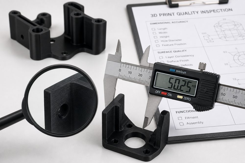
Introduction: The Importance of Quality Inspection
In 3D printing services, sample quality inspection is the last checkpoint for ensuring customer satisfaction. According to statistics, about 25% of customer complaints stem from quality issues, most of which can be prevented through a well-established inspection process. Building a systematic sample quality inspection system can effectively reduce quality risks, enhance customer trust, and lower rework costs.
1. Inspection Process Framework
1.1 Design Principles of the Inspection Process
When establishing an inspection process, the following principles should be followed:
- Comprehensiveness: Cover all aspects such as appearance, dimensions, and performance
- Operability: Inspection methods and standards should be clear and executable
- Traceability: Inspection records should be complete and retrievable
- Economy: Balance inspection costs with quality risks
1.2 Inspection Process Steps
A typical inspection process includes:
- Appearance inspection (visual inspection, magnifier inspection)
- Dimensional measurement (caliper, CMM, scanning)
- Performance testing (mechanical performance, functional testing)
- Record archiving (inspection reports, photo records)
- Decision to release or rework
2. Appearance Inspection Standards
2.1 Surface Quality Inspection
Inspection items include:
- Surface defects: Cracks, pores, poor fusion, delamination
- Surface roughness: Layer lines, support marks, stair-step effect
- Surface contamination: Dust, oil stains, residual powder
- Color uniformity: Color differences, spots, scorching
2.2 Geometric Integrity Inspection
Inspection items include:
- Feature integrity: Whether sharp corners and small features are complete
- Warping deformation: Whether flatness and straightness meet requirements
- Support residue: Whether support removal is thorough
- Post-processing quality: Effects of sanding, polishing, and spraying
2.3 Example of Appearance Inspection Standards
| Defect Type | Acceptance Criteria | Handling Method |
|---|---|---|
| Surface cracks | Not allowed | Rework or scrap |
| Pores (diameter < 0.5mm) | No more than 3 per 100cm² | Record, acceptable |
| Layer lines (depth < 0.1mm) | Acceptable if they do not affect function | Record, acceptable |
| Support residue | Not visible to the naked eye | Additional post-processing |
3. Dimensional Measurement Methods
3.1 Selection of Measuring Tools
Select measuring tools according to accuracy requirements:
| Accuracy Requirement | Recommended Tool | Measurement Range |
|---|---|---|
| ±0.5mm | Steel ruler, tape measure | Large-size measurement |
| ±0.1mm | Vernier caliper, height gauge | Standard dimensions |
| ±0.02mm | Micrometer, measuring gauge | Precision dimensions |
| ±0.01mm | Coordinate measuring machine | Complex geometry |
| ±0.005mm | Optical scanner | Full-size scanning |
3.2 Key Points for Dimensional Measurement
When performing dimensional measurements, pay attention to:
- Datum selection: Clearly define the measurement datum, consistent with the design datum
- Environmental control: The influence of temperature and humidity on measurement results
- Number of measurements: Measure key dimensions multiple times and take the average
- Measurement positions: Cover all key features and dimensions Next Step Is this close to what you need?
Submit a model, drawing, image or written notes. Engineers will review material, process, finishing and delivery based on actual use.