
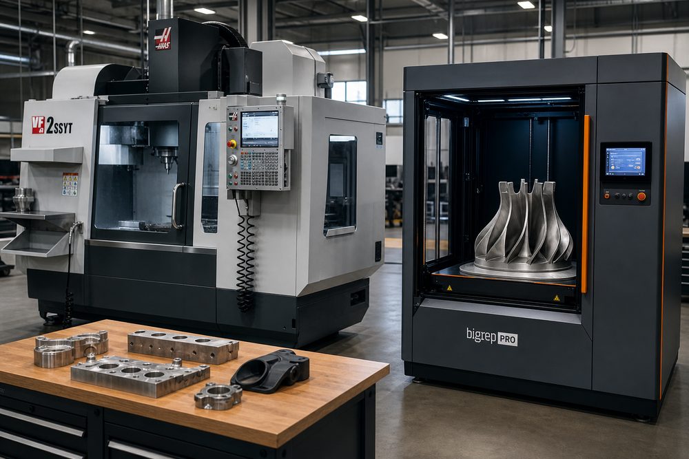
1. 3D Printing and CNC Are Not Substitutes, but a Division of Labor Determined by Geometric Complexity and Batch Size
In enterprise manufacturing scenarios, the most common misconception about 3D printing and traditional CNC machining is treating them as a competitive relationship of who is more advanced. In reality, the process decision is not driven by a single technical metric, but by part geometric complexity, material performance, dimensional accuracy, batch size, and delivery lead time. CNC excels in high precision, high repeatability, and mature material systems, making it especially suitable for metal structural parts, flat datum components, mating parts, and medium-to-high volume repetitive production. 3D printing, by contrast, is strong in complex geometries, rapid iteration, low fixturing cost, and near-net-shape manufacturing, making it especially suitable for flow-channel parts, lightweight structures, customized components, and prototyping stages. For engineers, the key question is not whether a part can be made, but which process can make it more economically and reliably.
From a technical standpoint, CNC can typically achieve stable dimensional tolerances of ±0.01 to ±0.05 mm, with surface roughness down to Ra 0.8 to 3.2 μm. Common FDM tolerance is around ±0.2 to ±0.5 mm, SLS/MJF can be controlled at the ±0.2 mm level, and metal SLM/LPBF parts can be machined after printing to bring critical dimensions back within ±0.05 mm. In other words, CNC is suitable for parts with clearly defined machining datums, regular geometries, and multiple mating surfaces, while 3D printing is suitable for parts where value is driven by geometry, machining fixtures are complex, or internal structures are constrained. When introducing a hybrid manufacturing strategy, enterprises should first determine whether the part value comes from dimensional accuracy or from structural innovation.
- CNC advantages: high precision, high repeatability, mature material systems, suitable for mating surfaces and high-load parts
- 3D printing advantages: no complex molds required, capable of producing internal cavities, honeycomb structures, conformal channels, and other complex geometries
- Core criterion: not the process itself, but the part's geometric complexity, lead time, and batch size
2. Process Selection Matrix: Five Dimensions That Turn 'Can Be Made' into 'Best Made This Way'
When building a process selection matrix, enterprises are advised to score parts across five dimensions: geometric complexity, dimensional accuracy requirements, material performance requirements, batch size, and delivery lead time. The higher the geometric complexity, the more obvious the advantage of 3D printing; the higher the accuracy requirement, the stronger CNC's advantage; the larger the batch, the lower CNC's unit cost is usually; and the tighter the lead time, the faster 3D printing can respond. For engineering teams, each dimension can be scored from 1 to 5, then weighted accordingly, for example: geometric complexity 30%, accuracy 25%, batch size 25%, lead time 10%, and material performance 10%. When the total score for 3D printing is more than 15% higher than CNC, the part should preferentially enter the printing route; otherwise, CNC should be preferred, or a hybrid route of printed blank plus machined finish should be adopted.
In real projects, the following rules are worth focusing on: when a part contains internal channels, undercut cavities, topology-optimized lattices, or thin-wall integrated structures, 3D printing can usually eliminate 3 to 5 process steps. When a part requires coaxiality, flatness, hole-position repeatability, and later assembly fit, CNC is more reliable. If the part has high unit value and high trial-and-error cost, a process with rapid iteration should be prioritized. If the part is intended for long-term mass production with stable geometry, CNC's amortization efficiency will be significantly higher. The value of professional platforms such as lantu3D lies precisely in comparing multi-process quotations, lead times, and post-processing capabilities within the same framework, avoiding decisions based solely on experience.
- High geometric complexity and many internal structures: prioritize 3D printing
- High requirements for accuracy, coaxiality, and surface finish: prioritize CNC
- As batch size increases, focus on machine cycle time, fixturing amortization, and post-processing time
- For prototyping, it is recommended to use printed parts to validate structure and CNC to validate functional surfaces
3. How to Calculate the Cost Break-Even Point: Fixed Cost, Variable Cost, and Rework Rate Determine the Critical Batch Size
The easiest place to make mistakes in process selection is looking only at unit price and ignoring the total cost structure. The essence of the cost break-even point is the intersection of the fixed costs and unit variable costs of two processes. It can be expressed with a simplified formula: total cost = fixed cost + unit variable cost × batch size. Take a complex aluminum alloy housing as an example. Assume the fixed cost for 5-axis CNC programming and tooling is 3,000 RMB, and the machining cost per part is about 260 RMB at a batch of 10, dropping to 120 RMB at a batch of 100. The fixed cost for SLS nylon printing is about 600 RMB, and the combined printing and post-processing cost per part is about 280 RMB at a batch of 10, dropping to 160 RMB at a batch of 100. Based on this model, the break-even point between CNC and SLS is around 19 parts: below 19 parts, SLS has the lower total cost; above 19 parts, CNC begins to show its scale advantage. This break-even point is not absolute and is affected by part complexity, material utilization, and rework rate.
From the perspective of material utilization, CNC material removal rates are commonly between 30% and 80%, and even higher for complex parts; material waste and tool wear must both be included. 3D printing typically achieves material utilization of 90% to 95%, but support removal, heat treatment, surface cleaning, and inspection costs must be considered. For metal printing, LPBF equipment can produce high-strength parts, but the build rate and post-processing costs are relatively high, making it suitable for complex low-volume parts. For plastic parts, MJF/SLS is often more economical than tooling for batches under 50, but when the batch approaches 200 or more, CNC unit cost can drop rapidly if multi-cavity fixtures or automated loading and unloading are available. In enterprise decision-making, do not look only at whether the printed unit price is low; look at whether the fixed cost can be sufficiently amortized by volume.
- Total cost logic: fixed cost + unit variable cost × batch size
- The critical batch size usually falls in the 10 to 50 piece range, depending on complexity and material
- 3D printing offers high material utilization, but post-processing and inspection costs must not be ignored
- As CNC batch size increases, fixture and program amortization can significantly reduce unit cost
4. Two Typical Cases: Complex Flow-Channel Parts Are Better Suited to Printing, While Precision Brackets Are Better Suited to CNC + Printing Hybrid Processes
Case 1 is an industrial cooling manifold. This part contains multiple internal flow branches. Traditional CNC would require splitting it into three pieces for machining and then welding or threaded assembly, which not only increases process steps but also introduces leakage risk. After adopting metal 3D printing (316L or AlSi10Mg), the internal flow channels can be formed in one piece, and only the flange and sealing surfaces are subsequently finish-machined by CNC. In actual projects, the single-part print time is about 18 to 26 hours, and heat treatment plus finish machining adds another 3 to 5 hours, but the total number of parts is reduced from 3 to 1, and assembly labor is reduced by more than 70%. If the batch is 5 to 15 pieces, the overall cost is usually lower than the traditional split-and-machine solution; when the batch exceeds 30 and the structure is stable, it is more appropriate to re-evaluate a cast blank plus machining solution.
Case 2 is an equipment mounting bracket. The part has a regular outer shape, but it requires high hole-position accuracy, flatness, and coaxiality, and it also carries a significant load. If it is directly 3D printed, the part can be prototyped quickly, but substantial machining is still needed afterward to correct the dimensions, which raises the cost. A better approach is to use 3D printing first for structural validation and assembly validation, confirm hole positions, interferences, and load paths, and then switch to CNC for batch production. If the bracket needs weight reduction internally, a hybrid route of printed preform plus machined datum surfaces can be adopted. This kind of combined approach is common in engineered parts and can balance development speed and production stability, especially for companies with frequent product iterations and short design freeze cycles.
- Flow-channel parts and internal-cavity parts: prioritize printing, and CNC-finish critical surfaces if needed
- Load-bearing brackets and precision mounting parts: prioritize CNC, with printing used for validation and weight-reduction trials
- The value of hybrid processes lies in reducing assembly part count, lowering leakage risk, and shortening iteration cycles
5. Hybrid Manufacturing Is Not Just 'Print First, Then Machine'; It Is a Reconstructed Process Chain Based on Functional Surfaces
True mature hybrid manufacturing is not about sending a printed part to a mill-turn machine for final trimming. Instead, it distinguishes between functional surfaces and non-functional surfaces from the design stage. Functional surfaces include assembly holes, sealing surfaces, bearing seats, locating datums, threaded holes, and high-precision mating surfaces; these should be assigned to CNC whenever possible. Non-functional surfaces can be formed geometrically by 3D printing, such as housing exteriors, cooling fins, lightweight lattice cuts, and internal channels. The advantage of this approach is that printing is responsible for creating complexity, while CNC is responsible for stabilizing accuracy. For metal parts, a machining allowance of 1.0 to 2.0 mm is recommended. For engineering plastic parts, if high-precision holes will be machined later, leaving 0.3 to 0.8 mm of allowance is more prudent.
In quality control, hybrid manufacturing must also account for thermal distortion and residual stress. Metal printed parts commonly exhibit deformation of 0.1% to 0.3% after removal from the machine, so heat treatment and stress relief are necessary steps. CNC machining, by contrast, must pay attention to fixture positioning errors and cumulative tool wear. For enterprises, the optimal workflow is usually: conduct a DFAM review during the design stage, use printing to validate the structure during the prototyping stage, adopt a printed blank plus CNC finish machining in trial production, and shift to a single CNC or tooling solution once the critical batch size is reached in mass production. This layered approach separates R&D risk, processing risk, and procurement risk, avoiding an all-in bet on a single process.
- Functional surfaces should be assigned to CNC, while complex geometry should be assigned to 3D printing; this division must be defined during the design stage
- For metal printing, leave 1.0 to 2.0 mm of machining allowance; for plastic parts, 0.3 to 0.8 mm is more prudent
- Hybrid processes must include stress relief, heat treatment, datum reconstruction, and inspection workflows
6. Implementation Recommendations for Enterprises: Replace Experience-Based Decisions with a Process Card + Cost Model + Supply Chain Response Approach
To truly implement hybrid manufacturing, enterprises should establish a standardized process card: part function, critical dimensions,
Submit a model, drawing, image or written notes. Engineers will review material, process, finishing and delivery based on actual use.