
Introduction
Developing a process plan is a core reflection of the technical capabilities of 3D printing service providers, directly determining product quality, delivery efficiency, and cost control. In the context of Industry 4.0, traditional experience-based process decision-making can no longer meet the needs of complex and changing manufacturing demands. Establishing a systematic process planning workflow has become a key step for 3D printing service companies to improve competitiveness. This article will explain the complete technical path of process plan development from the dimensions of requirement analysis, process selection, parameter optimization, and plan verification.
Process Plan Development Workflow Framework
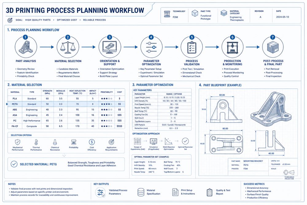
A complete process plan development workflow consists of six core steps: technical transformation of requirements, process type selection, material selection evaluation, parameter design and optimization, solution verification and confirmation, and process documentation. Each step has clear technical requirements and quality standards, forming a closed-loop management mechanism. In actual execution, the workflow may be trimmed according to project complexity and time urgency, but the core steps cannot be omitted.
Technical Transformation of Requirements
Technical transformation of requirements is the first step in process plan development. Its core is to convert customer business needs into quantifiable technical parameters. This includes: geometric feature analysis (dimensional accuracy, surface roughness, structural complexity), functional performance requirements (mechanical properties, temperature resistance, chemical stability), operating environment conditions (temperature, humidity, load), and batch size and cost constraints. In practice, requirement transformation often uses a requirement analysis form to ensure the accuracy and completeness of information transfer.
Process Type Selection
Process type selection requires comprehensive consideration of material characteristics, accuracy requirements, cost constraints, and delivery cycle. Mainstream 3D printing processes include: FDM fused deposition modeling (low cost, rich material options, suitable for functional verification and low-strength parts), SLA stereolithography (high precision, good surface quality, suitable for appearance parts and precision components), SLS selective laser sintering (no support required, excellent mechanical properties, suitable for functional parts), and SLM selective laser melting (for metal part manufacturing, suitable for high-performance structural parts). A process selection decision tree can quickly identify the optimal process solution.
Material Selection and Evaluation
Material selection should be comprehensively evaluated based on performance matching and process feasibility. Key evaluation dimensions include: mechanical property matching (tensile strength, impact toughness, hardness), physical property matching (temperature resistance, thermal conductivity, density), chemical stability (corrosion resistance, weather resistance), process adaptability (formability, shrinkage rate, support requirements), and cost availability (material price, procurement cycle). A material selection table can systematically record evaluation results and support decision traceability.
Parameter Design and Optimization
Parameter design is a core step in process plan development and directly affects product quality and production efficiency. Taking the FDM process as an example, key parameters include layer height, infill density, printing speed, nozzle temperature, and heated bed temperature. Parameter optimization should follow these principles: when accuracy is the priority, choose a small layer height (0.1–0.15 mm); when strength is the priority, increase infill density (≥50%); when efficiency is the priority, increase layer height (0.3–0.4 mm) and printing speed (≥60 mm/s). A parameter optimization matrix can quickly match the optimal parameter combination for typical application scenarios.
Determining the Process Window
The process window refers to the adjustable range of key parameters while ensuring product quality. Determining the process window requires orthogonal experimental design to systematically examine parameter interactions. Taking the SLS process for PA12 material as an example, the laser power window is 30–45 W, the scanning speed window is 1500–2500 mm/s, and the powder layer thickness window is 0.1–0.15 mm. After the process window is determined, parameter adjustment rules can be formulated accordingly to address material batch variations and environmental changes.
Solution Verification Methods
Solution verification is a necessary step to ensure the feasibility of the process plan. Verification methods include: specimen testing (mechanical properties, dimensional accuracy, surface quality), first article inspection (appearance, function, assembly), and small-batch trial production (stability, consistency). The verification process should record key parameters and quality data to establish a baseline for process capability. If verification fails, parameters must be adjusted and revalidated until quality requirements are met.
Process Plan Documentation
Process plan documentation is an important carrier for technical accumulation and knowledge reuse. A complete process plan document includes: process plan overview, requirement transformation records, basis for process selection, material selection evaluation, parameter design方案, verification test report, quality control key points, and risk response measures. Documentation should follow a standardized template to ensure information completeness and traceability. Process plan documents should be incorporated into the enterprise knowledge management system to support rapid reference for subsequent projects.
Practical Case: Prototype Manufacturing of an Aircraft Engine Blade
An aircraft engine manufacturer needed to produce a set of blade prototypes for wind tunnel testing. Requirement analysis showed: blade length 120 mm, profile accuracy requirement ±0.15 mm, surface roughness Ra ≤ 3.2 μm, and the need to withstand airflow temperatures of 300°C. After process selection evaluation, although the SLM process could meet the performance requirements, it was too costly and time-consuming; the SLA process met the accuracy and surface quality requirements but lacked sufficient temperature resistance; ultimately, a high-temperature resin SLA process was selected, with a post-processing high-temperature-resistant coating added.
During the parameter optimization stage, the optimal parameter combination was determined through DOE experiments: layer height 0.05 mm, infill density 100%, support density 60%, and post-curing time 30 minutes. Verification testing showed: dimensional accuracy ±0.12 mm, surface roughness Ra = 2.8 μm, and successful temperature resistance testing. The project delivery cycle was shortened by 40%, costs were reduced by 35%, and customer satisfaction improved significantly.
Common Issues and Solutions
Issue 1: Requirement information
Submit a model, drawing, image or written notes. Engineers will review material, process, finishing and delivery based on actual use.