
Introduction: Utility Air Has Not Yet Become a Separate Ledger Among the Four Accounts
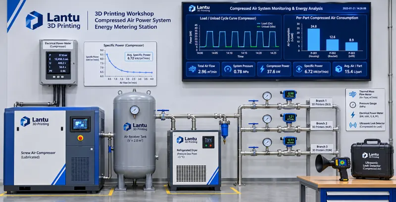
Over the past two years, lantu3D has refined its workshop energy accounting: electricity costs are split by peak/off-peak periods and demand charges; shielding gas for build chambers is allocated in m³ per part; recirculating cooling water is tracked by make-up water volume and concentration cycles; and carbon footprint is allocated by functional unit and shared-build distribution. Yet one utility has long remained hidden in the common "utility power" expense pool, with neither dedicated metering nor a per-part accounting basis: utility compressed air for pneumatic valves, powder conveying, blasting, blow-off, and cylinders. An 11 kW screw compressor operating 4,000 hours per year incurs more than CNY 30,000 in electricity costs even at CNY 0.70/kWh. If its load factor is only 35%, nearly half of that energy may be wasted in unloaded idling. More problematic, compressed-air leaks do not leave visible marks like water leaks. They appear only as gradually declining pressure, sluggish pneumatic valves, or inconsistent blasting force, and are eventually classified as "occasional equipment abnormalities." This article is not an energy-saving slogan, but a reproducible method based on specific power, load factor, leakage rate, submeter readings, and per-part utility-air consumption, bringing compressed air into the same energy ledger as electricity, water, gas, and carbon.
1. Separate the Two Gases First: Shielding Gas and Utility Air Must Not Be Accounted Together
A metal LPBF workshop has at least two gas systems with entirely different accounting bases. Calculating them in one table will inevitably produce errors. Process shielding gas is argon or nitrogen supplied to the build chamber. Its performance indicators include 99.999% purity, chamber oxygen content of 1,000 ppm or below (below 500 ppm for aerospace parts), and a dew point of ≤ −40 °C. It is measured in m³ per part, and its cost varies with chamber purge cycles and chamber volume. Utility compressed air is generated by compressors and distributed through a 0.6–0.8 MPa network to pneumatic valves, powder conveying equipment, blasting cabinets, air guns, and cylinders. Its performance indicators include pressure, flow, oil and water content class, and electricity consumption for air generation. It is measured in Nm³ per part. The former is a process input condition; the latter is an energy utility. This article addresses only the latter. Solid particle content, pressure dew point, and oil content of compressed air are controlled according to ISO 8573-1 classifications and fall within equipment availability management. They have been discussed elsewhere and are cited here only as prerequisites for acceptable air quality at the point of use.
2. Specific Power and Load Factor: Oversizing Is the Largest Hidden Waste
Compressor efficiency is not judged by appearance or nameplate rating, but by specific power: the electrical power consumed to produce 1 m³/min of compressed air, expressed in kW/(m³/min). A fixed-speed screw compressor with an output of 1.6 m³/min and input power of 11 kW has a specific power of approximately 6.9. Top-tier efficiency models can achieve below 6.5, while older units in service for more than eight years, or units with clogged inlet filters or slipping belts, commonly reach 8.5–10. The first accounting step is to simultaneously record electrical power P (kW) and air output Q (m³/min) during stable full-load operation, then calculate SP = P/Q. Record continuously for three working days and use the median value rather than relying on nameplate data.
The second indicator is the load factor, η = T_load / (T_load + T_unload). This is where variable-speed and fixed-speed compressors differ: during unloading, a fixed-speed compressor motor continues running, consuming approximately 30%–50% of full-load power while producing almost no air. In high-mix, low-volume workshops, air demand is pulsed—blasting may run intensively for ten minutes, while only intermittent pneumatic-valve movement occurs for the remainder of the time. If a large 3.0 m³/min compressor is selected based on peak demand, measured η is often below 40%. Engineering criteria are as follows: η continuously between 60% and 85% for two weeks is healthy; 40%–60% calls for air-use scheduling adjustments first, such as consolidating blasting and blow-off into the same time window; below 40%, combined with an existing receiver volume below 0.5 m³, indicates that a variable-speed compressor or a large-and-small dual-compressor configuration is more economical than simply replacing the unit with a larger one. Example: for an 11 kW compressor with η=0.35 and unloaded power of 4 kW, annual unloaded energy consumption at 4,000 h is approximately 4000×(1−0.35)×4 = 10,400 kWh, equal to nearly CNY 7,300 in electricity cost from this item alone.
3. Leakage Rate: Convert a “Hissing Sound” into Nm³/h and CNY/Year
Leaks occur primarily at compression fittings, hoses, solenoid valves, filter-regulator units, quick-connect fittings, and chamber door seals, and increase approximately linearly with pressure. A practical quantitative method is a shutdown pressure-hold test: close all air-consuming endpoints, charge the system to 1.1 times the operating pressure without exceeding component ratings, and record the total volume V (m³) of the receiver and piping network, the pressure drop ΔP (MPa) over 30 minutes, and ambient atmospheric pressure P_atm (0.101 MPa). Convert this to standard-condition leakage flow using Q_leak ≈ V·ΔP/(P_atm·t), where t is 0.5 h. Example: with V=0.8 m³ and a 0.06 MPa pressure drop over 30 minutes, Q_leak ≈ 0.8×0.06/(0.101×0.5) ≈ 0.95 Nm³/min—roughly equivalent to a 1.0 m³/min small compressor operating at full load all day. This alone can explain why total-meter air consumption does not decline.
The criteria should be fixed in writing: Q_leak at ≤5% of rated air output is acceptable; 5%–10% should be included in the monthly leak-inspection plan; and >10% requires production-line shutdown and corrective action. Locate leaks using an ultrasonic leak detector at fittings, soapy water on valve bodies, or a thermal mass flow meter installed downstream of the main meter for baseline comparison during nighttime shutdowns. Tag each leak and record its location, estimated orifice size, and readings before and after repair to establish a leakage ledger. The pressure-hold test must be repeated after repair to close the loop; otherwise, “resolved” is merely a different label.
4. Submetering and Point-of-Use Breakdown: From Main Meter to Branch Meters
One compressor power meter plus one main-pipe flow meter provides only an average value and offers no optimization target. A three-tier submetering system is recommended. The first tier is the air-generation side: a compressor input power meter plus a main-pipe vortex flow meter, used to calculate specific power and total air generation. The second tier is the branch side: divide the network by point of use into at least three branches—build-equipment air circuits (pneumatic valves, powder conveying, recoater cylinder), post-processing air circuits (blasting, blow-off, pneumatic grinding), and shared auxiliary air circuits (dust-collector pulse cleaning, valve instrumentation). Install thermal mass flow meters on each branch with a 1-minute sampling interval. The third tier is the event side: time-align pressure-transmitter readings with MES work-order status and build layer numbers to identify which operation is pulling down network pressure.
All measurements must be standardized to reference conditions of 20 °C, 101.325 kPa, and 0% relative humidity, with the conversion basis documented in the ledger. If field instruments display actual volumetric flow, readings must be converted using measured pressure and temperature; otherwise, data from different seasons cannot be compared. Set one pressure point upstream and one downstream of the dryer and filters. A sustained differential pressure of >0.05 MPa should trigger filter-element replacement, preventing insufficient pressure from being misdiagnosed as inadequate compressor capacity. The reconciliation difference between the sum of branch-meter readings and the main-meter reading should be ≤8%. Any greater deviation indicates an unregistered bypass, meter inaccuracy, or leakage.
5. Per-Part Utility-Air Consumption: Accepted Delivered-Part Basis and Shared-Build Allocation
The denominator for per-part utility-air consumption must be consistent with electricity cost, water consumption, and carbon footprint accounting: it should be the number of accepted delivered parts during the accounting period, not the number of printed parts or the number of build jobs started. The numerator is adjusted according to allocability: q = (Q_total − Q_leak − Q_nonprod) / N_good, where Q_total is the cumulative standard-condition air generation from the main meter during the accounting period; Q_leak is the leakage rate converted from pressure-hold tests and extrapolated by operating hours; Q_nonprod is separately metered non-production air use, such as maintenance air guns and air borrowed by other workshops; and N_good is the number of accepted delivered parts during the same period. Without these three deductions, q will be artificially inflated by weekend shutdowns and expanding leaks, making month-to-month comparisons meaningless.
Shared-build allocation should use proxy weights consistent with those used for recirculating water and carbon footprint, rather than dividing equally by part count. For each part, construct a weight wi from “scan time × layer count × support and build-plate volume correction factor.” Allocate the common pool—such as pre-purge piping blow-off, pneumatic actions during build-plate preheating, air circuits associated with witness coupons, and standby baseline air consumption—according to wi. Directly assign separately attributable consumption, such as blasting time dedicated to a specific part or individually recorded blow-off, to that part. Example: for a build containing 12 parts, with a common pool of 8.4 Nm³ and total weights of 42, a part with w=5 receives 1.0 Nm³. Adding 0.6 Nm³ for dedicated blasting gives q=1.6 Nm³/part. Ledger fields should include at minimum: accounting period, main-meter reading, leakage quantity, non-production air use, accepted part count, weighting-table version, allocation results, and reviewer. Only by sharing the same accounting-period boundary as electricity, water, and carbon can these values be combined into a complete per-part energy cost card.
6. Release Criteria and Dashboard: Link Air Consumption to Build Layer Numbers
Air-consumption accounting must ultimately support release control. Three mandatory criteria should be written into work instructions. First, the process pressure criterion: pause the process if branch pressure during building falls below 0.55 MPa or fluctuates by >0.08 MPa within 1 minute. Record the corresponding build layer number, chamber position, and scan-task ID at the time of occurrence, then review recoating images, oxygen-content curves, and witness-coupon results for the affected chamber parts. Utility disturbances can only support release decisions when tied to specific parts; this follows the same logic as linking voltage sags to layer numbers. Second, the quality prerequisite criterion: if the pressure dew point and oil-content class at the point of use do not meet the agreed ISO 8573-1 grade, the corresponding batch of utility air must not be included in the accepted denominator for q, preventing oil- or moisture-contaminated air from being counted as effective output. Third, the trend criterion: for the same process and weight basis, if q rises by >15% compared with the average of the previous eight builds, or if specific power SP rises by >10%, freeze subsequent production scheduling for that machine type and trigger leak inspection and filter verification.
The dashboard should display only five action-driving indicators: specific power SP (kW/(m³/min)), load factor η (%), leakage rate (as a percentage of rated air output), per-part utility-air consumption q (Nm³/part), and per-part air-electricity cost (CNY/part, = q × SP / 60 × electricity price). Generate monthly trends and issue weekly exception lists to equipment owners. For a platform such as lantu3D that covers the full lifecycle from design blueprint to physical delivery, upgrading utility compressed air from a “facility condition” to a measurable, allocable, and release-controlled energy medium completes the final utility ledger after electricity, water, shielding gas, and carbon.
Conclusion
Utility compressed-air waste does not result from one failed machine, but from four missing accounting bases: failure to separate shielding gas from utility air, failure to measure specific power and load factor, failure to convert leaks into flow and cost, and failure to fully deduct non-product air before allocating total air generation to accepted parts. The recommended implementation sequence is to first conduct a shutdown pressure-hold test to establish a leakage baseline; then install three-tier submeters and operate them for two full weeks; use η and SP to determine whether compressor configuration should be changed; and finally incorporate q and shared-build weights into the same energy ledger while establishing the three release criteria. At that point, the compressor is no longer simply the machine “always running” in the corner. It becomes a verifiable data chain that can answer: how many Nm³ were allocated to this build, how much additional electricity cost was incurred, and on what basis the parts are permitted for release.
Submit a model, drawing, image or written notes. Engineers will review material, process, finishing and delivery based on actual use.