
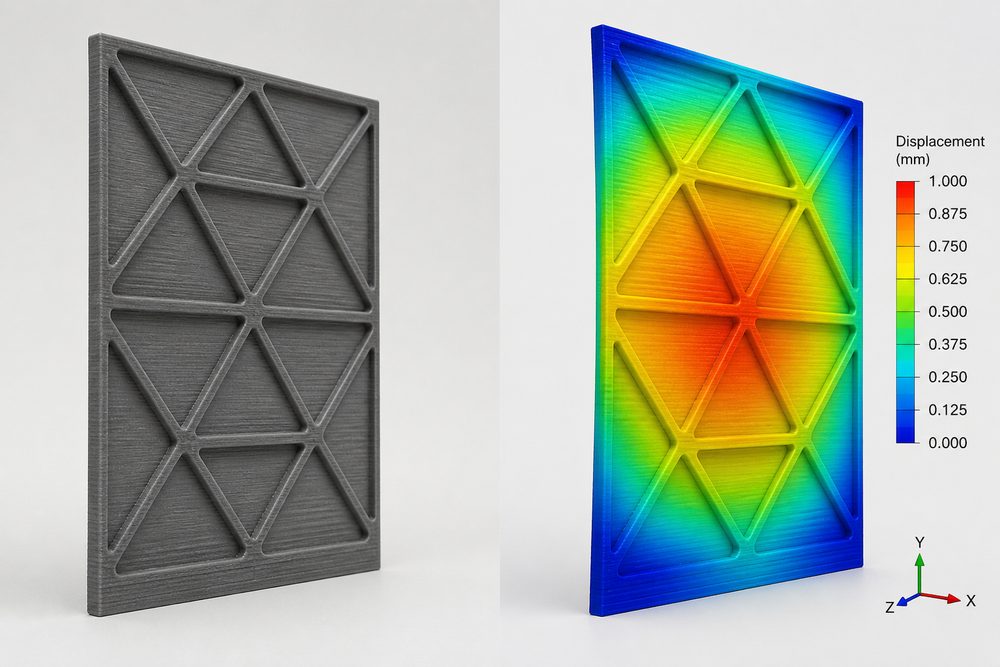
Introduction: Challenges in Thin-Wall Structural Design
Thin-wall structures are an important means of achieving lightweight design in 3D printing, and are widely used in aerospace, automotive, consumer electronics, and other fields. However, improper wall thickness design can lead to issues such as deformation and cracking during printing, as well as insufficient stiffness in use. This article systematically introduces thin-wall structural design methods to help engineers find the optimal balance between lightweighting and structural strength.
1. Minimum Wall Thickness Limits for Different Processes
1. FDM Process Wall Thickness Parameters
The minimum wall thickness in FDM is affected by factors such as nozzle diameter, layer height, and material properties:
| Parameter | Minimum Value | Recommended Value | Description |
|---|---|---|---|
| Single-wall thickness | 0.8mm | 1.2-1.5mm | At least 2 extrusion line widths |
| Vertical wall thickness | 0.4mm | 0.8-1.0mm | Along the Z-axis, lower strength |
| Horizontal wall thickness | 0.8mm | 1.2mm or above | In the XY plane, higher strength |
Practical example: In the design of a drone arm, using PLA material and a 0.4mm nozzle, the wall thickness was designed to be 1.2mm, and the print success rate increased from 62% to 98%.
2. SLA Photocuring Process Wall Thickness Parameters
SLA offers higher resolution and can achieve thinner wall thicknesses:
- Minimum wall thickness: 0.4mm (standard resin), 0.6mm (engineering resin)
- Wall thickness in overhanging areas needs to be increased by 20-30%
- Large-area flat structures need to consider the risk of warping
3. SLS Powder Sintering Process Wall Thickness Parameters
The minimum wall thickness in SLS depends on powder characteristics and laser energy:
- PA12 material: minimum wall thickness 0.7mm, recommended 1.0mm or above
- Metal powder (AlSi10Mg): minimum wall thickness 0.8mm, recommended 1.5mm or above
- The wall thickness-to-height ratio should be controlled within 1:8
2. Methods for Calculating Wall Thickness and Stiffness
1. Thin Plate Stiffness Formula
Bending stiffness calculation formula for thin-wall structures:
D = E·t³ / [12(1-ν²)]
Where: D is the bending stiffness (N·m), E is the elastic modulus (Pa), t is the wall thickness (m), and ν is Poisson's ratio.
Key conclusion: stiffness is proportional to the cube of wall thickness; increasing wall thickness by 10% increases stiffness by about 33%.
2. Comparison of Material Stiffness
| Material | Elastic Modulus (GPa) | Poisson's Ratio | Relative Stiffness with 1mm Wall Thickness |
|---|---|---|---|
| PLA | 3.5 | 0.36 | 1.0 (baseline) |
| ABS | 2.1 | 0.35 | 0.60 |
| PA12 | 1.7 | 0.40 | 0.49 |
| Carbon Fiber PLA | 6.0 | 0.30 | 1.71 |
3. Practical Stiffness Optimization Case
A certain industrial equipment housing design:
- Original design: ABS material, 2mm wall thickness, insufficient stiffness, deformation occurred during use
- Optimization plan 1: Increase wall thickness to 3mm, weight increases by 50%, stiffness improves by 237%
- Optimization plan 2: Keep 2mm wall thickness and add ribs, weight increases by 15%, stiffness improves by 180%
- Final choice: Plan 2, balancing lightweighting and stiffness requirements
3. Rib Layout Strategy
1. Choosing Rib Types
| Type | Applicable Scenarios | Advantages | Disadvantages |
|---|---|---|---|
| Straight ribs | Simple flat plate structures | Simple design, easy to print | Limited unidirectional stiffness improvement |
| Grid ribs | Large-area flat surfaces | Biaxial stiffness, uniform stress distribution | Greater weight increase |
| Honeycomb ribs | High lightweighting requirements | High stiffness-to-weight ratio | Complex design, requires software assistance |
2. Rib Dimension Parameters
The rib height is generally 3-5 times the wall thickness:
- Rib plate thickness: 0.8- Next Step Is this close to what you need?
Submit a model, drawing, image or written notes. Engineers will review material, process, finishing and delivery based on actual use.