
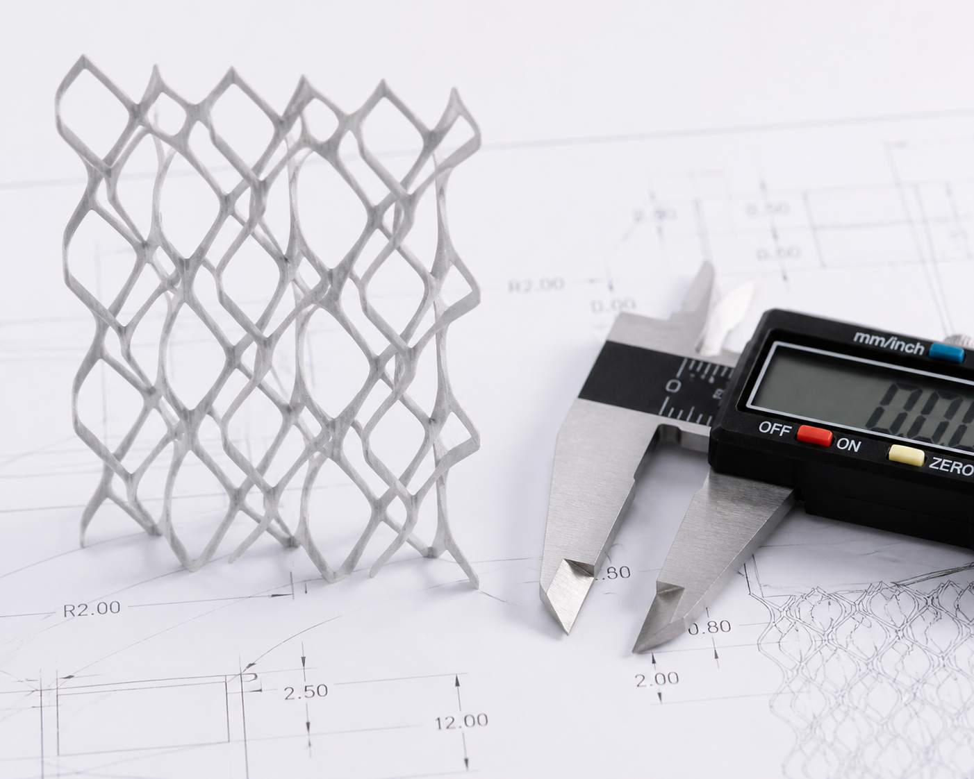
Basic Principles of Thin-Walled Design
Thin-walled structures are one of the most challenging features in 3D printing design. Thin walls not only reduce part weight and save material but also enable functions unachievable by traditional manufacturing (such as thin-walled flow channels and heat dissipation fins). However, excessively thin wall thickness can lead to printing failures (such as warping, cracking, and collapse) or result in deformation and damage during subsequent use. Therefore, understanding the thin-wall manufacturing capabilities of different 3D printing processes is key to successful design.
The core of thin-wall design is finding a balance between "manufacturability" and "functionality". Manufacturability is influenced by factors such as process resolution, material properties, and printing parameters; functionality depends on the part's mechanical requirements, assembly requirements, and operating environment. Generally, wall thickness should not be less than the minimum feature size of the process, while also considering the part's loading conditions and service life. For critical load-bearing components, wall thickness should also allow for a sufficient safety factor.
Comparison of Minimum Wall Thickness for Various Processes
The limitations on minimum wall thickness vary significantly across different 3D printing processes. In the FDM process, due to the layer-by-layer deposition of filament, the minimum wall thickness is limited by the nozzle diameter; typically, a 0.4mm nozzle yields a minimum wall thickness of 0.8-1.0mm (2-2.5 times the line width), while a 0.2mm nozzle can achieve a minimum wall thickness of 0.4-0.5mm. For SLA/DLP photopolymerization processes, the resolution is determined by pixel size and light spot diameter; typically, the minimum wall thickness can reach 0.3-0.5mm, and high-resolution equipment (such as 4K/8K LCD) can even achieve 0.2mm. The minimum wall thickness for the SLS powder sintering process is typically 0.7-1.0mm, limited by powder particle size (usually 40-80μm) and sintering strength.
The limitations on minimum wall thickness for metal 3D printing (SLM/EBM) are more stringent. The SLM process typically employs a laser spot size of 20–40 μm, allowing for a minimum wall thickness of 0.3–0.5 mm; however, considering thermal stress and deformation control, it is recommended that the minimum wall thickness be no less than 0.8–1.0 mm. Due to the larger electron beam spot size (approximately 0.1–0.2 mm) in the EBM (Electron Beam Melting) process, the recommended minimum wall thickness is no less than 1.0–1.5 mm. For special applications, wall thickness can be further reduced through process optimization (such as adjusting scanning strategies or using supports), but this increases printing difficulty and the risk of failure.
Suspended Span and Support Design
Thin-walled structures are often characterized by overhang features, where the wall surface forms a certain angle with the vertical direction. The overhang angle is a critical factor influencing print quality and support requirements. For the FDM process, overhangs with angles less than 45° typically do not require supports and can be printed directly; overhangs between 45° and 60° require careful design, possibly necessitating reduced layer thickness or adjusted print speed; overhangs exceeding 60° almost always require the addition of supports, otherwise significant sagging and deterioration of surface quality will occur.
For thin-walled overhanging structures, support design is particularly critical. If supports are placed beneath a thin wall, removing them will leave marks on the wall surface, affecting both appearance and functionality. Solutions include: 1) using soluble support materials (such as PVA or HIPS) to prevent surface damage caused by manual removal; 2) designing the thin wall as a self-supporting structure by increasing wall thickness or modifying the geometry to keep the overhang angle below 45°; 3) designing a "sacrificial layer" beneath the thin wall, which is removed after printing to achieve a smooth surface. For the SLA process, due to the fluidity of liquid resin, restrictions on overhang angles are stricter, and supports are generally required when the angle exceeds 30°.
Detail Reproduction Capability and Resolution
Detail reproduction capability is an important metric for measuring the accuracy of 3D printing processes, directly affecting the quality of thin walls and fine structures. The XY resolution of the FDM process is determined by the stepper motor step size and belt drive ratio, typically ranging from 0.1 to 0.2 mm; the Z resolution is determined by the layer thickness, typically ranging from 0.1 to 0.3 mm. For SLA/DLP processes, the XY resolution is determined by the pixel size; for a 4K LCD (3840×2160) with a print area of 120×68 mm, the pixel size is approximately 0.03 mm, resulting in extremely high theoretical resolution. However, the actual resolution is also influenced by factors such as light scattering and material properties, typically achieving 0.05 to 0.1 mm.
In terms of detail reproduction, SLA/DLP processes are significantly superior to FDM processes, capable of printing features such as fine textures, text, and hollow structures. For instance, SLA can clearly print text 0.2mm in width, walls 0.3mm in thickness, and small holes 0.5mm in diameter. The FDM process is relatively weaker in detail reproduction; text 0.5mm in width may appear blurry, and walls thinner than 0.8mm may be discontinuous. Due to the granular nature of the powder, the SLS process has detail reproduction capabilities falling between those of FDM and SLA, with a minimum resolvable feature size of approximately 0.5-1.0mm.
Wall Thickness Uniformity and Stress Control
Wall thickness uniformity is an important consideration in thin-walled structural design. Non-uniform wall thickness leads to inconsistent cooling rates, resulting in internal stress and warping deformation. In FDM printing, thick-walled sections cool slowly and shrink more, while thin-walled sections cool quickly and shrink less. This difference generates tensile stress in the wall thickness transition zones, which can lead to cracking in severe cases. Therefore, wall thickness should be kept as uniform as possible during design, or a gradual transition design should be adopted in wall thickness transition zones to avoid abrupt changes.
For SLA/DLP printing, uneven wall thickness leads to inconsistent curing shrinkage, which also generates internal stress. Furthermore, the degree of cure in thick-walled sections is typically lower than in thin-walled sections (due to limited light penetration depth), resulting in degraded mechanical properties in the thick-walled areas. Solutions include: 1) designing "lightening holes" or "honeycomb structures" in thick-walled sections to reduce material accumulation; 2) adopting a "gradual wall thickness" design to ensure smooth wall thickness transitions; 3) optimizing printing parameters (such as increasing exposure time or using post-curing) to ensure thick-walled sections are fully cured.
Stiffeners and Structural Optimization Design
When a design requires thin-walled structures but there are concerns about insufficient strength, ribs can be used. Ribs can significantly improve the stiffness and strength of thin-walled structures without significantly increasing weight and material. The design principles for ribs include: the rib thickness should be 0.5-0.7 times the wall thickness to avoid stress concentration; the rib height should not exceed 3-5 times its thickness to prevent buckling; and the rib spacing should be 2-3 times the rib height to balance stiffness and weight.
For 3D printing, rib design can also be optimized by incorporating process characteristics. For example, ribs in FDM printing should be oriented along the printing direction (typically the XY plane) to enhance interlayer bonding strength; ribs in SLA printing can feature "zigzag" or "wave-shaped" designs to enhance structural aesthetics while improving stiffness. Furthermore, "lattice structures" can be used to replace solid thin walls, maintaining high stiffness and strength while reducing weight. The unit cell size of a lattice structure is typically 2-10 mm, with a strut diameter of 0.5-2 mm; specific parameters need to be determined based on stress analysis.
Effect of Post-processing on Thin-walled Structures
Post-processing of thin-walled structures requires special care, as thin-walled parts are prone to deformation or damage during processes such as sanding, polishing, and sandblasting. For FDM-printed thin-walled parts, fine-grit sandpaper (400 grit or higher) should be used during sanding, and pressure must be controlled to avoid deformation caused by excessive local force. For SLA-printed thin-walled parts, due to the relative brittleness of the material, sanding is more likely to cause chipping and cracking; therefore, wet sanding is recommended, and the amount of sanding should be minimized.
Sandblasting is an effective method for improving the surface quality of thin-walled parts, but attention must be paid to the blasting pressure and the selection of abrasives. For thin-walled parts, it is recommended to use low pressure (0.2-0.3 MPa) and fine abrasives (such as glass beads) to avoid impact deformation. For thin-walled parts requiring high dimensional accuracy, the post-processing allowance should be controlled within 0.1-0.2 mm, and precision machining (such as CNC milling) should be employed to ensure final dimensions. Furthermore, thin-walled parts should undergo stress relief treatment (such as annealing) after post-processing to eliminate residual stresses induced by machining.
Design Checklist and Verification Methods
After completing the design of thin walls and fine structures, it is recommended to use the following checklist for verification: 1) Is the minimum wall thickness greater than the process limit? 2) Does the overhang angle exceed the process limitations? 3) Is the wall thickness transition smooth? 4) Are fine features larger than the process resolution? 5) Is the rib design reasonable? 6) Is there sufficient assembly clearance? 7) Is post-processing allowance reserved? 8) Does the stress analysis indicate stress concentration?
Verification methods include: 1) using slicing software to conduct a "print preview" to check the cross-section of each layer, confirming that the thin-walled structure can be printed continuously; 2) using Finite Element Analysis (FEA) software for strength and deformation analysis to confirm that the thin-walled structure will not fail under service loads; 3) printing a 1:1 prototype for physical verification, particularly for critical parts, where prototype verification is the most effective method for identifying design issues. Through systematic inspection and verification, the success rate of thin-walled structure design and product quality can be significantly improved.
Submit a model, drawing, image or written notes. Engineers will review material, process, finishing and delivery based on actual use.