
Introduction: A Fraction-of-a-Second Voltage Dip Can Ruin an Entire Build Chamber
A single metal laser powder bed fusion (LPBF) build chamber commonly runs for 20 to 80 hours. If the grid experiences a voltage sag lasting 80 to 200 ms during that time, the laser may enter instantaneous undervoltage protection, galvanometer servo motors may lose position, and the recoater blade may stop mid-stroke. Even if the control system reports no fault, melt-pool energy density may already have drifted outside the process window, and that layer may become the starting point of lack-of-fusion defects that scrap the entire part. Most workshops record such incidents as “occasional equipment stoppages” but never treat power-supply disturbances as measurable, assessable process variables. lantu3D regards the full lifecycle from blueprint to physical-part delivery as an auditable data chain: power quality is not a facilities issue, but an upstream input that determines whether a part can be released.
1. Define the Boundaries First: Electricity Billing, Utility Support, and Power Quality
Existing discussions commonly focus on two levels. The first is the electricity-billing level: time-of-use tariffs, demand management, power-factor penalties, and production scheduling to avoid peak demand, all intended to reduce cost per kilowatt-hour. The second is the utility-support level: inert-gas purity and pressure, recirculating-water flow and quality, dust-collection differential pressure, and whether switchgear and grounding are properly implemented, all intended to ensure continuous availability of auxiliary systems. This article addresses the third level—the power-quality and supply-disturbance mitigation level: voltage-sag magnitude and duration, harmonic distortion, three-phase imbalance, transient surges, and high-frequency noise. Its purpose is to answer: “What power events did this build experience during production, and did any event exceed the process release criteria?” The three levels may share the same meter, but their criteria are entirely different: billing focuses on kWh and demand, utility support focuses on pressure and flow, and power quality focuses on millisecond-scale waveforms and thresholds.
2. How Disturbances Reach the Melt Pool: Four Mechanisms and Observable Traces
Thresholds can be established only by mapping disturbances to process consequences. A voltage sag (typically a drop to 70%–90% of nominal voltage for 20 ms to 1 s) first affects the laser power supply and chiller compressor, appearing as reduced laser output or protective shutdown and leading to discontinuous melt tracks and interlayer lack of fusion. A short interruption (>1 s) triggers a control-system safety shutdown; even if the build resumes, the remelt region may form a band of abrupt hardness and microstructural changes. Harmonics (primarily generated by variable-frequency drives, rectifiers, and UPS systems, with THDv and THDi as key indicators) cause torque pulsation in servo drives and galvanometer motors as well as heating in power modules, manifesting over time as gradual drift in positioning repeatability and scan trajectories. Three-phase imbalance shifts the neutral point and raises phase voltage on one phase, reducing the service life of heating and motor loads. Surges and high-frequency noise may pass through control lines and cause encoder miscounts or communication packet loss; their traces are unexplained alarms in system logs rather than visible defects. Observable traces should include the event timestamp, minimum voltage, duration, current layer number, actual laser power, recoater-axis position, and chamber oxygen content. Without this cross-reference table, the impact boundary of an event cannot be determined afterward.
3. Measurement Strategy: What to Install, Where to Install It, and Which Standards to Use
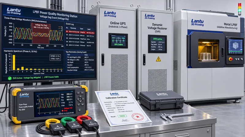
A three-tier measurement-point arrangement is recommended: Level 1 at the transformer low-voltage incoming supply to capture plant-wide background quality; Level 2 at the outgoing feeder of the LPBF equipment distribution cabinet to capture disturbances actually experienced by the machine; and Level 3 at the laser power supply and galvanometer control circuit to capture residual voltage at sensitive loads. Meters must comply with IEC 61000-4-30 Class A measurement methods. Sags, swells, and interruptions should be assessed using IEC 61000-4-11 and SEMI F47 immunity curves; harmonics should follow IEC 61000-3-2 / 3-12 and IEEE 519 THDv limits (typically 5% on the low-voltage side and 3% for an individual harmonic); fluctuations and flicker should follow IEC 61000-4-15; and surge immunity should follow IEC 61000-4-5. For sampling, voltage sags require at least 1 kHz RMS refresh and retention of waveforms from 200 ms before through 1 s after each event. Steady-state harmonics should be assessed using a 10-minute aggregation window and P95 statistics. A practical initial set of criteria is: residual voltage below 85% at the equipment end for more than 20 ms is a Class A event; THDv above 5% continuously for 10 minutes is a Class B event; and three-phase voltage imbalance above 2% is a Class C event. Every event must be linked to a build layer number.
4. From Events to Release Decisions: Incorporating Power Data into Quality Records
Power-quality data must enter the same evidence chain as witness coupons, inspection lots, and model hashes; otherwise, it remains merely an equipment log. A three-tier decision process is recommended. First, if an event occurs outside the build window—during standby, preheating, or powder removal—it should be recorded but requires no expanded inspection. Second, if it occurs during the build window but both residual voltage and duration remain within the equipment's verified immunity envelope, established from the manufacturer curve or machine-specific process validation, it should be recorded and the melt-track image for that layer should be reviewed. Third, if it exceeds the envelope or causes laser shutdown, the build must be immediately quarantined. All parts in the chamber should undergo CT or metallographic sampling, with particular focus on lack of fusion and porosity in the three layers above and below the event layer. No concessionary release is permitted without conforming evidence. Eight mandatory data fields are: event ID; meter measurement-point ID and calibration validity; start and end timestamps; minimum residual voltage/THD/imbalance; corresponding build and layer number; equipment immunity-envelope version; disposition conclusion; and reviewer. ALCOA+ principles should ensure that raw waveforms cannot be overwritten and that timestamps share the same source as MES work orders, preventing retrospective data entry.
5. Mitigation Hierarchy and Validation: Isolate First, Compensate Second, Upgrade Last
Mitigation should be prioritized by cost-effectiveness. The first level is topology isolation: place laser power supplies, galvanometer controls, and high-start/stop loads such as chillers, dust collectors, and air compressors on separate feeders, separate transformers, or at minimum separate phases, preventing compressor starts from causing sags on the same feeder. Verify grounding and equipotential bonding, and use single-end grounding of cable shields to eliminate high-frequency noise coupling. The second level is point-of-use compensation: install online UPS systems or dynamic voltage restorers (DVRs) for laser and control circuits, explicitly defining whether coverage is limited to control circuits or includes the laser's main power. Most UPS systems cannot support kilowatt-class lasers; selection must therefore be based on measured inrush current and power factor, followed by loaded verification of transfer time below 10 ms. Where harmonics exceed limits, install active harmonic filters according to measured spectra rather than blindly adding capacitors, which may resonate with system impedance and amplify harmonics. The third level is incoming-supply modification: adjust transformer taps, increase short-circuit capacity, or install voltage regulators or active front ends. Every modification level must be validated: record seven days of background data under both no-load and full-load conditions, build three chambers of the same batch of standard test specimens before and after modification, and compare melt-track-width standard deviation, density, and surface roughness. One simulated voltage sag, following equipment-approved safety procedures, should also confirm that a Class A event is correctly recorded and intercepted. Only when all three conditions are met—power events are reproducible, part data show no difference, and the record chain is auditable—may the measure be incorporated into a controlled process card.
6. Implementation Checklist and Common Misconceptions
For implementation, verify the following items one by one: ① Do measurement points cover the incoming supply, equipment feeder, and sensitive-load levels? ② Are the meters' Class A method compliance and calibration certificates current? ③ Are pre-event and post-event waveforms retained for voltage sags rather than only a single alarm record? ④ Is every event automatically linked to the build and layer number? ⑤ Does the equipment immunity envelope have version control and a validation report? ⑥ Are quarantine and expanded-inspection rules for Class A events written into the release SOP? ⑦ Are comparative data from the same batch of standard test specimens available before and after mitigation? ⑧ Are raw waveforms, disposition conclusions, and reviewers included in the ALCOA+ record chain? There are three common misconceptions: treating power-factor correction as power-quality mitigation—the former saves electricity costs, while the latter protects builds; installing only a main meter without examining the equipment end—an acceptable upstream supply does not guarantee an acceptable feeder output; and assuming a UPS can protect the entire machine—most protect only the control circuit. Another misconception is to reject every build affected by a voltage sag. Criteria should come from a validated immunity envelope, not from the number of alarms.
Conclusion
For 3D printing workshops performing long-duration continuous builds, supply disturbances are upstream process inputs on the same level as powder batch, oxygen content, and geometry repair. Elevating power quality from “facility stability” to a “measurable release variable” requires three specific deliverables: a three-tier measurement-point system and event-waveform library established in accordance with IEC 61000-4-30; graded thresholds and equipment immunity envelopes defined according to SEMI F47 and IEEE 519; and an evidence chain linking event timestamps to build layer numbers and expanded-inspection conclusions. With these three elements in place, an 80 ms voltage dip is no longer an unexplained “occasional stoppage,” but an engineering record that can be reviewed, assessed, and used to determine part release. This is the implementation on the power-supply side of the end-to-end auditable capability, from design blueprint to physical-part delivery, advocated by lantu3D.
Submit a model, drawing, image or written notes. Engineers will review material, process, finishing and delivery based on actual use.