
Introduction: Being Printable Does Not Mean Surviving in a Tribological Pair
As 3D-printed parts move from prototypes to functional components, they are increasingly used in applications involving relative motion, including sliders, guideway bushings, pump and valve sealing faces, fixture locating surfaces, and mating surfaces of conformal-cooling inserts. At this stage, common acceptance-sheet entries such as “dimensions compliant, density 99.5%, tensile strength meets requirements” are insufficient to predict service life. Peaks and valleys on LPBF as-built surfaces with Ra values of 6–20 μm can rapidly cut the mating component during run-in; alternating hard and soft regions formed by interlayer melt-pool boundaries can cause nonuniform wear; lack-of-fusion defects and near-surface porosity become spallation initiation sites under contact stress; and the interlayer direction of polymer printed parts can cause wear rates to vary several-fold by orientation. Many teams treat “blasting + polishing” as the endpoint of tribological delivery, yet specify neither stabilized post-run-in roughness nor PV limits, wear rates, and failure criteria. As a result, parts from the same batch may exhibit service lives differing by an order of magnitude on customer equipment. Tribological validation is not merely an additional hardness report; it is a reproducible test design that specifies contact conditions, surface condition, sampling orientation, acceleration factors, and failure thresholds.
1. Define the Duty Profile Before Defining the Test: Do Not Validate All Parts with One Set of Parameters
Break service inputs into five recordable fields: normal load F (N), relative velocity v (m/s), contact configuration (point/line/area; reciprocating/rotary/unidirectional), medium and temperature (dry friction/oil lubrication/aqueous solution/dust, 20–200°C), and motion cycles and duty cycle. Use these inputs to calculate nominal contact pressure p and PV value (MPa·m/s), and identify whether operation is continuous or intermittent. As an example criterion, PA12 SLS sliders under dry friction are recommended to remain within 0.1–0.3 MPa·m/s; above 0.5 MPa·m/s, temperature rise can soften the surface layer and lead to adhesive wear. Polished and surface-strengthened 316L can be used at 1–3 MPa·m/s under lubricated conditions. Test plans must cover three stress levels, such as 0.6/1.0/1.4 times rated PV, with at least five specimens per level; otherwise, it is impossible to distinguish random spallation from systematic failure that rises monotonically with load. It is unacceptable to run only one favorable parameter set, obtain an attractive wear-track image, and conclude that wear resistance is good.
2. Specimens and Surface Condition: Four Variables Unique to Printed Parts
Tribological testing is far more sensitive to specimen condition than conventional tensile testing. The following four items must be included on the specimen card: ① Sampling orientation—test one set of specimens perpendicular to the build direction and another parallel to it. LPBF metal parts may show elongation differences of 20–40%, and wear rate may likewise be orientation-dependent; testing only one orientation conceals the weakest section. ② Surface condition—establish separate groups for as-printed, blasted, ground/polished (recommended Ra ≤ 0.8 μm), and coated/nitrided conditions. “Final parts” and “standard coupons” must not be combined in the same conclusion. ③ Post-processing history—record whether heat treatment, HIP, and impregnation sealing have been completed, as whether pores are closed significantly affects spallation initiation. ④ Counterbody—fix and document material, hardness, roughness, and radius of curvature. Retain two untested specimens from each batch. Before run-in, record Ra/Rz/Rpk using a profilometer, then remeasure at the same location after run-in. Many apparent “wear-resistant” conclusions merely reflect worn-flat asperity peaks; evaluation must be based on wear volume rather than wear-track width alone.
3. Test Methods and Measurable Outputs
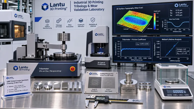
Select standard methods according to the contact configuration: reciprocating ball-on-disk/pin-on-disk tests may reference ASTM G133 and ASTM G99; abrasive wear may use ASTM G65; coating adhesion may use cross-cut testing (ISO 2409) or pull-off testing (ISO 4624 / ASTM D4541). Record friction coefficient and wear volume simultaneously. Report at least five outputs: steady-state friction coefficient μ (the mean of the final 20% of cycles after run-in, with standard deviation); wear volume ΔV (mm³, preferably measured by 3D profilometry/white-light interferometry rather than 2D wear-track width); specific wear rate W = ΔV/(F·L) (mm³/N·m); counterbody wear volume; and time to failure (μ increase >30%, abrupt increase in vibration/noise, temperature rise exceeding the defined threshold, or coating spallation area >5%). Weigh specimens before and after testing using a balance with 0.1 mg resolution, convert mass loss to volume when density is known, and verify with profilometry. Polymer parts must be conditioned at 23±2°C and 50±5% RH for 24 h before weighing; otherwise, moisture-related mass changes can obscure milligram-level wear loss. For metal parts, an additional industrial CT or metallographic inspection is recommended to confirm whether subsurface cracks propagate along melt-pool boundaries beneath the wear track.
4. Release Criteria for Surface Engineering and Coatings
When the substrate alone cannot withstand tribological service, common approaches include shot peening/roller burnishing to introduce compressive stress, nitriding/carburizing to increase surface hardness, and thermal-spray or PVD coatings to reduce adhesion. In such cases, release criteria must be upgraded from “coating thickness” to dual criteria covering “interface + tribology.” Determine thickness from the average of five metallographic cross-section measurements and specify tolerance, such as 20±5 μm. Cross-cut adhesion shall achieve Class 0–1, or pull-off strength shall be ≥15 MPa; porosity and unmelted particles shall be counted from metallographic fields of view. This must be followed by 10⁴–10⁶ wear cycles, with no through-coating spallation and W not exceeding one-third of the baseline part value. A particular concern is that near-surface porosity in additively manufactured parts can release gas during high-temperature PVD or remelting of thermal-spray layers, forming pinholes. Vacuum degassing and pore-sealing verification should therefore be performed before coating. Otherwise, a coating may pass adhesion testing yet blister after three months in service, with the issue incorrectly attributed to overly severe customer operating conditions.
5. Limits of Accelerated Validation and Life Extrapolation
Acceleration does not simply mean doubling rotational speed. Arrhenius-type temperature acceleration or a load-index model, W = K·p^a·v^b·t, may be used, but a and b must be fitted using measured data from at least three stress levels, with R² ≥ 0.9 and no systematic curvature in the residuals. The extrapolation factor should generally not exceed 2–3 times the highest tested stress. Beyond this range, or when the failure mechanism changes, such as mild oxidative wear transitioning to adhesion/spallation or full-sheet coating delamination, extrapolation is immediately invalid and long-duration validation at rated conditions is required. Weibull analysis is recommended for life assessment, reporting characteristic life and shape parameter. A shape parameter
Submit a model, drawing, image or written notes. Engineers will review material, process, finishing and delivery based on actual use.