
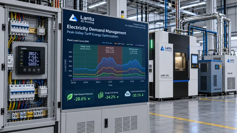
Introduction: Two Charges on the Electricity Bill, but Most Workshops Watch Only One
An industrial electricity bill generally consists of two components: an energy charge and a basic charge. The former is billed according to actual electricity consumption (kWh), while the latter is based on the month's maximum demand (kW) or transformer capacity. Most 3D printing workshops focus all of their energy-saving efforts on reducing kilowatt-hours while overlooking demand charges. A simultaneous startup of all equipment, or a ten-minute overlap between one oven and two metal printers during the morning shift, can raise the monthly maximum demand by more than 30%. This charge then remains in effect throughout the subsequent billing cycle.
Time-of-use electricity pricing presents an even more immediate issue. In most regions, commercial and industrial tariffs divide the day into four periods: critical peak, peak, shoulder, and off-peak. The price difference between critical-peak and off-peak periods commonly reaches 2.5 to 4 times. For a metal LPBF machine rated at 8 to 15 kW, shifting an entire 12-hour build job to an off-peak period can reduce per-part electricity costs more than any minor adjustment of process parameters.
1. Map the Load Profile Before Discussing Optimization
Any electricity optimization effort must begin with measurement. It is recommended that a power meter with data-logging capability be installed at the workshop incoming switchgear, with a sampling interval of no more than one minute and continuous data collection for at least two weeks, covering a complete production week. Key metrics to extract include the shape of the daily load profile and the timing of peak demand, the individual power draw and operating patterns of major equipment, base-load power during standby conditions, and the daily average and fluctuation range of the power factor.
Measured data typically reveals several common issues. The first is excessive base load: after a printer completes a build, its temperature-holding system, dust collector fan, chiller, and air compressor may continue operating without intervention, causing nighttime base load to reach 40% to 60% of daytime demand. The second is overlapping startup surges: multiple high-power units are switched on together before a shift, creating the day's highest power peak. Although this peak may last only a few minutes, it determines the basic charge for the entire month. The third is low power factor: workshops with numerous inductive loads often operate at a power factor of 0.75 to 0.85, below the utility's assessment threshold of 0.90, resulting in substantial monthly power-factor adjustment charges.
2. Demand Management: Flatten Peaks Rather Than Simply Reducing Total Consumption
The core logic of demand control is staggered startup and shutdown combined with power-cap constraints. Implementation has three layers. The first is equipment-level interlocking: set permitted operating periods and concurrent-operation limits for each type of high-power equipment in the workshop energy management system. For example, build machines and heat-treatment furnaces should not start simultaneously, and the compressors in air compressors and chillers should not load within the same minute. Interlocking does not reduce total output; it only changes how power is distributed over time.
The second layer is demand warning and automatic load shedding: set an alarm threshold slightly below historical maximum demand, such as 90% of the historical maximum. When rolling-average power approaches this threshold, the system automatically postpones non-critical loads according to preset priorities. Oven heating and powder drying, for example, should be deferred first, while active printing jobs must never be interrupted. The third layer is startup ramping: introduce high-power heating loads in stages to prevent instantaneous surges caused by multiple heating elements being energized at the same time.
3. Off-Peak Production Scheduling: Move Flexible Processes to Low-Price Periods
Not all processes can be moved freely. Rigid and flexible processes must be distinguished. Once a build process begins, it must run continuously to completion; a power interruption would result in scrapped parts and lost powder. It is therefore semi-rigid: it cannot be interrupted, but its start time can be selected. Powder drying, sieving, part annealing, shot blasting, cleaning, and drying are not time-sensitive and are fully flexible processes. They should be scheduled as a priority during off-peak periods.
In practice, scheduling rules can be designed as follows: first, work backward from the delivery deadline to determine the latest possible start time for each build job. If starting at the beginning of the lowest-price period still meets the deadline, schedule the build to start during that period. Schedule flexible processes such as annealing and drying entirely during off-peak and shoulder periods. During critical-peak periods, retain only low-power operations such as inspection, assembly, and packaging. For a workshop with two metal printers, simply adjusting build start times can typically reduce monthly energy charges by 15% to 25%.
4. Power Factor and Specific Equipment-Side Improvements
Low power factor should be addressed first at the equipment level rather than by directly installing a compensation cabinet. Common causes include motors operating under light load for extended periods, where power factor deteriorates significantly below 40% loading; high no-load losses in aging transformers; and harmonics generated by variable-frequency drives that cause measurement deviations. Targeted measures include replacing oversized motors that operate under light load, adding variable-frequency control to continuously operating fans and pumps, and installing active harmonic filters on circuits with severe harmonic distortion. After equipment-side improvements are completed, if the power factor remains below 0.90, centralized reactive-power compensation equipment can be installed in the distribution room. Its capacity should be determined based on the measured reactive-power deficit to avoid overcompensation.
There is also room for optimization during equipment selection. When purchasing printing equipment, consider standby power rather than build power alone. Compared with a machine using 10 kW during building and 3 kW in standby, a machine using 11 kW during building but only 0.8 kW in standby may consume less electricity annually in low-utilization, small-batch production environments. Similarly, chillers should be selected with load-adaptive control to avoid frequent cycling of fixed-speed compressors.
5. Establish an Executable Closed Loop for Electricity Management
Institutionalizing the measures above requires four elements. First is submetering: at minimum, build equipment, post-processing equipment, and utility loads such as compressed air, chilled water, and dust collection should be metered separately. Otherwise, the actual source of energy savings cannot be identified. Second is KPI development: establish energy consumption per part (kWh/part) and electricity consumption per unit of output value, track them monthly, and compare them after normalization by production volume. Third is anomaly alerting: automatically notify the responsible equipment owner when daily base load rises by more than 15% above the historical average or when the power factor falls below 0.88. Fourth is a review mechanism: each month, break down the electricity bill into energy charges, basic charges, and power-factor adjustment charges, assign each to specific equipment and behaviors, and develop an improvement list for the following month.
Conclusion
Electricity optimization in a 3D printing workshop is fundamentally not about simply using less electricity; it is about using electricity at the right time and with the right power profile. First, use submetering to understand the load profile and demand composition. Then flatten peaks through interlocking and load shedding, shift flexible processes to off-peak periods through production scheduling, improve power factor through equipment-side measures, and finally institutionalize improvements using energy-consumption-per-part metrics. This approach does not require major investment, yet it can reduce electricity costs by a visibly meaningful amount while providing traceable source data for subsequent carbon-footprint accounting.
Submit a model, drawing, image or written notes. Engineers will review material, process, finishing and delivery based on actual use.