
Introduction: Why the Same Model Can Still Be Made Wrong
In actual on-demand manufacturing delivery, rework and disputes rarely result from inadequate equipment capability. More often, they arise because the documentation is unclear. The same STEP model may be sent to three factories and result in three build orientations, three support strategies, and three post-processing interpretations. The dimensions may all pass inspection, yet the part still fails to assemble. The issue is not the model geometry itself, but the information beyond the model: what the drawing should communicate, who should communicate it, and at what level of detail.
After more than a century of development, conventional machining has established a stable drawing language: views, sections, dimension chains, GD&T feature control frames, surface roughness symbols, title blocks, bills of materials, and technical requirements. Additive manufacturing has directly inherited this language, but not the process consensus behind it. In subtractive manufacturing, the stock material is defined and machining allowances are determined by process engineers. In additive manufacturing, however, parts are built from the ground up, and build direction, interlayer bonding, and thermal history all affect final performance. Leaving all this information to be interpreted independently by the production team transfers quality risk to the least controllable stage. lantu3D treats technical-document standardization as a governance priority equal to process parameters throughout the full lifecycle from design to physical delivery.
1. Four Additional Questions Additive Manufacturing Drawings Must Answer
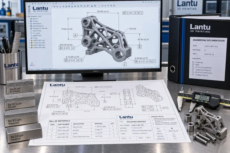
In addition to conventional geometry and tolerances, an additive manufacturing drawing suitable for production must explicitly answer four questions: first, the build direction or permitted orientation range; second, the areas where support residue is permitted and the areas where it must be removed; third, the definition of surface condition, including which surfaces remain as-printed, which require machining, and how roughness is to be evaluated; and fourth, the acceptance basis, including whether acceptance is based on test coupons or the part itself, and whether inspection is sampling-based or 100% inspection. These four items have no corresponding standard fields in conventional drawings and are generally added through written technical requirements or 3D PMI annotations.
Without the first item, the production team will select an orientation based on its own practices, leaving the roundness of critical holes, the distribution of stair-step effects, and strength direction uncontrolled. Without the second, support remnants may either be excessively ground away and damage dimensions or remain in internal channels and cause subsequent blockage. Without the third, the parties' understanding of an “acceptable surface” may differ by two roughness grades. Without the fourth, acceptance decisions devolve into experience-based negotiation.
2. Title Blocks: Standardizing Non-Negotiable Information
The title block is the identity card of a drawing. In addition to standard fields such as drawing number, name, material, scale, designer, reviewer, and date, additive manufacturing drawings should include six additional fields: material grade and powder batch requirements, build process code (such as LPBF, SLS, FDM, or SLA), machine category or layer-thickness range, post-processing condition (as-printed/stress-relieved/machined/surface-treated), data revision number and model file hash, and applicable standard number. The model file hash is frequently overlooked, yet it is the lowest-cost way to prevent situations in which “the model was changed but the drawing was not.” Any one-byte change to a file changes its hash, enabling direct verification of whether the drawing and model are from the same revision.
The title block should also clearly specify units and projection method. In cross-regional collaboration, confusion between first-angle and third-angle projection can produce mirrored parts, while mixing metric and imperial units is even more hazardous. Projection symbols and the unit system should be fixed in the title block rather than left for drawing readers to infer.
3. Bill of Materials (BOM): Documentation Boundaries for Integrated Builds
When parts are built in a single operation as an assembly, such as a mechanism with moving hinges or a fixture containing multiple integrally printed parts, the BOM serves to declare the delivery boundary. It should identify each subcomponent's item number and name, whether it can be separated, who performs the separation operation, whether post-separation machining is required, and the identification number and placement of accompanying test coupons, if required. For assemblies that must be separated for shipment, the BOM should also specify separation planes and reassembly datums.
A common mistake is to manage multiple integrally printed parts as a single material code, which invalidates inventory management and traceability. The correct approach is for the integrated assembly to share one manufacturing identification number during production, while retaining item-level codes and quantities for subcomponents in the BOM. Delivery and assembly can then be traced at the subcomponent level. This preserves manufacturing executability without compromising material master-data consistency.
4. Engineering Technical Requirements: From Adjectives to Verifiable Clauses
Technical requirements are a frequent source of disputes because many clauses cannot be objectively assessed. Statements such as “the surface shall be smooth,” “no obvious deformation is permitted,” and “strength shall meet service requirements” can lead to different conclusions by different inspectors. Engineering-oriented wording requires every technical requirement to include three elements: the metric, the method, and the acceptance criterion.
For example, instead of writing “the surface shall be smooth,” write: “The sealing surface shall have Ra ≤ 6.3 μm, evaluated in accordance with GB/T 1031 using a sampling length of 0.8 mm; measure three locations in the illustrated Area A and use the maximum value.” Instead of writing “no obvious deformation is permitted,” write: “In the free state, the parallelism between datum A and datum B shall not exceed 0.15 mm, specified in accordance with GB/T 1182; stress-relief annealing shall be completed before inspection, followed by conditioning for no less than 4 hours in an environment of 22 ± 2 °C.” Instead of writing “strength shall meet requirements,” write: “Accompanying test coupons shall be produced using identical process parameters and the same furnace heat treatment. Room-temperature tensile strength shall be no less than 950 MPa and elongation after fracture no less than 10%. Testing shall comply with GB/T 228.1, with no fewer than three specimens per batch.”
Default values for unspecified tolerances and surface conditions should also be defined. Package clauses such as “Unspecified dimensional tolerances shall comply with GB/T 1804-m; unspecified geometrical tolerances shall comply with GB/T 1184-K; unspecified surfaces shall remain as-printed, with no mandatory Ra requirement” are recommended to prevent widespread unmarked requirements from becoming impossible to assess.
5. The Primary and Secondary Relationship Between Models and Drawings: MBD and PMI
As product manufacturing information (PMI) and model-based definition (MBD) become more widely adopted, there has been debate over whether 2D drawings are still necessary. In practice, the approach should be phased. For parts with a single source, a single process, and long-term stability, a fully 3D data set can serve as the sole controlled authority, with dimensions, tolerances, surface requirements, and process notes directly annotated on the model to reduce interpretation ambiguity caused by 2D projections. For parts involving outsourcing, multiple processes, or assembly interfaces, 2D drawings should still be retained as the lowest common denominator: they do not depend on a specific software version and can be opened and checked by anyone.
Regardless of the approach, one iron rule must be followed: the same information must be defined in only one location. If a dimension appears in both 3D annotations and a 2D drawing, changes can create inconsistencies, and inspectors cannot determine which source takes precedence. It is recommended that the 2D drawing be designated as the sole controlled source for geometry and tolerances, with the 3D data set used only for manufacturing programming; or vice versa. In either case, this must be explicitly stated in the documentation, and dual definitions must not be permitted.
6. Version Control and Change Traceability
The value of technical documentation lies in traceability. A revision sequence should be established for each drawing. Use a “major revision.minor revision” format: changes to geometry or tolerances increment the major revision, while annotation-only changes or presentation improvements increment the minor revision. Each change must record the reason for the change, its scope of impact, including whether it affects work in progress, inventory, or delivered parts, and whether first article inspection must be repeated. Change request forms, impact-analysis conclusions, and revised files should be retained as a linked set of records. Obsolete revisions should be marked as obsolete but must not be physically deleted, ensuring that historical deliveries remain traceable.
The document-distribution stage also requires a closed loop: the distribution list, receipt confirmation, and obsolete-document retrieval record should be reconcilable. The root cause of many quality issues is not that a document was written incorrectly, but that the shop floor is still using the previous revision.
Conclusion
Standardizing technical documentation for additive manufacturing essentially means writing process consensus into verifiable clauses. Title blocks standardize non-negotiable process and revision information, BOMs declare delivery boundaries, technical requirements evolve from adjectives into measurable and reviewable criteria, and version control ensures that every delivery can be traced back to the complete document status at that time. Once this foundation is solid, equipment capability can be reliably converted into delivery capability.
Submit a model, drawing, image or written notes. Engineers will review material, process, finishing and delivery based on actual use.