
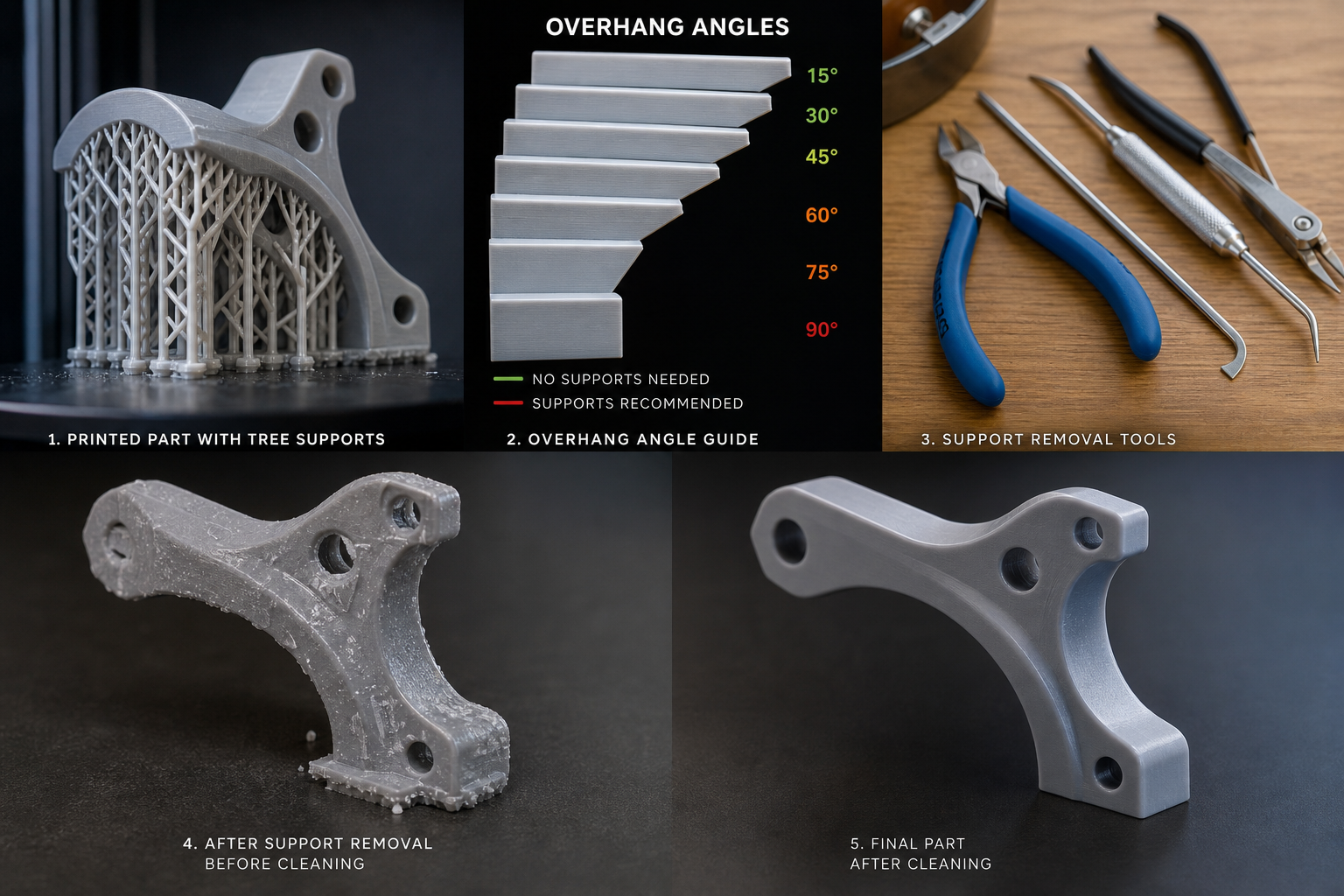
I. Overhang Angle Threshold: First Determine Whether Support Is Needed
The first step in support structure design is not to draw supports immediately, but to determine whether the model has self-supporting capability. For FDM/FFF processes, the most commonly used engineering rule of thumb is the 45° rule: when the outward overhang angle of a given layer relative to the previous layer is less than 45°, stable formation can usually be achieved through the support of the underlying material and cooling; once it exceeds 45°, the risks of sagging, stringing, and edge collapse increase significantly. For machines with stronger cooling and lower layer heights (such as 0.12 mm), some PLA materials can extend the threshold to 50° or even 55°; for materials with more pronounced shrinkage such as ABS and PA, the practical support-free angle is often more conservative, and it is recommended to control it within 40° to 45°. For SLA/DLP processes, the logic for judging overhang angles is different, with the focus on island layers, cantilevers, and separation forces caused by sudden cross-sectional changes; typically, when a cross-section completely loses overlap with the layer below, support should be considered first.
- Common FDM rule of thumb: 45° as the dividing line; PLA can be slightly more permissive, while ABS/PA should be handled more conservatively.
- Bridging is not the same as an overhanging surface; short-span bridges can often be printed without supports by optimizing the fan, speed, and line width.
- SLA/DLP should focus first on island layers and peel area, not angle alone.
II. Optimizing Support Contact Points: Strong Enough to Hold, but Minimal Surface Damage
Support contact points determine the balance between stability and post-processing difficulty. If the contact point is too small, the support may detach or vibrate during printing, especially on parts with a high aspect ratio, sharp corners, and locally heavy centers of gravity; if it is too large, obvious indentations will be left on the surface, significantly increasing sanding work. For FDM, the contact diameter generally starts from 0.3 mm; small detailed parts can use 0.2 to 0.4 mm, while heavier or high-temperature materials can be increased to 0.5 to 0.8 mm. For SLA resin parts, the common range is 0.2 to 0.6 mm; functional parts typically use around 0.4 mm, while appearance parts should be kept as close as possible to 0.2 to 0.3 mm. The contact-point location is also critical: avoid front-facing display surfaces, mating surfaces, sealing surfaces, and snap-fit edges, and prioritize the back side, ribs, chamfers, and areas that can be machined later.
- Use small contact points on detail surfaces and medium contact points on load-bearing areas; avoid one-size-fits-all settings.
- Place contact points on non-visible surfaces, machinable stock allowance surfaces, or hidden functional surfaces whenever possible.
- For long, thin-walled parts, multiple small contact points are better than a few large ones, as they reduce local stress concentration.
III. Easy-to-Remove Support Design: Evolving from “Can Be Removed” to “Easy to Remove”
If support design only considers strength, post-processing often comes at a high cost. A more engineering-oriented approach is to move support removal into the modeling stage: control the contact area, gap, and cutting direction between the support and the model so that removal is predictable and controllable. Common FDM support gaps are 0.2 to 0.35 mm, with the exact value depending on nozzle diameter, layer height, and material adhesion. With a 0.4 mm nozzle and 0.2 mm layer height, PLA can start testing from a 0.2 mm gap, while PETG should be increased to 0.3 mm or more because PETG adheres much more strongly to supports. SLA resin parts can reduce breakage risk through "light touch points + thin pillars"; typical pillar diameters can be graded from 0.8 to 1.5 mm, with primary load-bearing supports thicker and secondary supports thinner. For complex parts, the removal sequence should also be planned in advance: remove peripheral and low-risk supports first, then handle critical areas to avoid surface tearing caused by sudden load.
- Common FDM support gaps are 0.2 to 0.35 mm; PETG and flexible materials require larger gaps.
- The removal direction should follow the structural load path to avoid edge chipping caused by sideways prying.
- Complex parts can use a graded "main support + secondary support" strategy to improve stability and reduce removal difficulty.
IV. Different Process Logics: FDM, SLA, and SLS Cannot Share the Same Rules
There is no universal template for support design; strategies vary completely by process. FDM supports mainly provide temporary backing for molten material, so the focus is on overhang angle, bridge span, cooling conditions, and nozzle path. SLA/DLP supports carry the suspended loads and peel forces generated during photopolymerization, so the focus is on cross-sectional changes, resin drainage, and pull-off force. SLS/MJF usually do not require traditional supports, but powder surrounding still limits the forming stability of some very thin features, and warpage caused by heat accumulation is similar to support-related issues, so it must be addressed through build orientation and wall-thickness design. Based on actual production experience, a 20 mm bridge span in FDM can often be printed directly if the fan airflow is sufficient and the line width is controlled at 0.9 to 1.0 times the nozzle diameter; the same geometry in SLA may require denser support points, otherwise cracks may occur during peeling due to sudden cross-sectional changes between layers. For platform-based manufacturing services, front-end review must be divided by process rather than sending all models to the same default support algorithm.
- FDM emphasizes thermal stability and bridging performance; SLA emphasizes peel force and island control; SLS/MJF focuses more on orientation and thermal deformation.
- The number of supports, contact-point size, and build angle for the same part may be completely different across processes.
- Platform services should build process-specific parameter libraries instead of relying on a single default slicing preset.
V. Minimizing Support Marks: Coordinated Control Through Orientation, Splitting, and Process Parameters
Support marks are not determined only by contact-point size; more often, they result from the combined effect of part orientation, support strategy, and print parameters. For appearance parts, the most effective method is often not to make the supports finer, but to reorient the part so that the visible surfaces are moved to the side with the fewest supports. For example, with a decorative shell featuring curved surfaces, printing it flat may create more than 20 support contact points on the front face; tilting the part by 35° to 45° can reduce front-side contact points to fewer than 5 while moving the marks to internal rib areas. In FDM, reducing layer height to 0.12 mm, lowering outer wall speed to 25 to 35 mm/s, and increasing cooling can reduce the stepped appearance after support removal. In SLA, small contact points, inclined orientation, and local thickening of transition areas can reduce mushroom-like marks. For parts that must maintain appearance quality, common approaches include split printing followed by bonding, or reserving 0.2 to 0.5 mm of finishing allowance in the support-contact area for subsequent machining, coating, or polishing.
- An orientation angle of 35° to 45° can significantly reduce front-facing support contact points.
- Appearance parts should reserve 0.2 to 0.5 mm of post-processing allowance for sanding and coating repair.
- For large aesthetic structural parts, split printing plus bonding is often more reliable than one-piece printing with extensive supports.
VI. Practical Case Study: From Failed Samples to Stable Mass Production
One industrial enclosure project used PLA+FDM printing, with part dimensions of approximately 260 mm × 180 mm × 70 mm. The top featured a ring of undercut ribs. In the initial plan, the part was printed flat, with support coverage reaching 28%. After removal, obvious indentations remained on the front surface, and subsequent sanding took more than 40 minutes per part. After re-evaluation, the part was tilted at 42° and the supports were changed to a tree-like branching structure. The contact points were reduced from 0.6 mm to 0.35 mm, support coverage dropped to 12%, visible support marks on the appearance surface were reduced by about 70%, and post-processing time was shortened to 15 minutes per part. In another SLA functional-part case, a flow-channel component with an internal cavity failed because too few support points were used, leading to local detachment at 60% build height. After optimization, three sets of main supports were added at the cavity inlet, the end of the cantilever, and below the center of gravity. With a pillar diameter of 1.2 mm and contact points of 0.4 mm, the peel-failure rate dropped from about 18% to less than 2%. This case shows that support design cannot rely solely on the software-generated result; it must be corrected a second time based on geometry, center of gravity, load path, and post-processing capability.
- For enclosure-type parts, tilted orientation can significantly reduce support coverage and sanding time.
- For SLA flow-channel parts, preventing island-layer detachment is critical; insufficient support is more likely to cause scrap than excessive support.
- Before mass production, verify 1 to 3 sample parts to confirm support removal, surface quality, and dimensional stability.
Conclusion
The core of 3D printing support structure design is not to add as much support as possible, but to balance overhang angle, contact-point size, removal convenience, and post-processing cost. In engineering practice, a self-supporting threshold of around 45° can be used first to eliminate unnecessary supports, and then the parameters can be refined by process type: FDM focuses on bridging, cooling, and support gaps; SLA focuses on island layers, peel force, and pillar grading; appearance parts should reduce marks through orientation, part splitting, and allowance design. For manufacturers, support optimization directly affects print success rate, rework rate, and labor cost. For platform-based 3D printing services, building process-specific support parameter libraries, sample validation workflows, and post-processing standards is often more effective than simply upgrading equipment for improving delivery stability.
Submit a model, drawing, image or written notes. Engineers will review material, process, finishing and delivery based on actual use.