
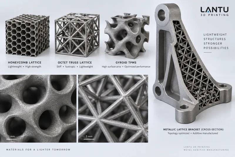
Introduction: When “Weight Reduction” Becomes a Hard Requirement, Why Lattice Structures Deserve Serious Attention
In the design of structural components for aerospace, new energy vehicles, and high-end consumer electronics, weight is often a hard constraint that affects the entire system: every kilogram reduced allows an aircraft to carry more payload, an electric vehicle to gain several kilometers of range, and a handheld device to improve grip comfort and thermal management space. The traditional approach of “drilling weight-reduction holes” quickly encounters stiffness limitations—the more holes there are, the more severe the stress concentration becomes. Lattice and honeycomb structures have therefore re-entered the engineering field of view: they replace solid bulk material with periodically arranged unit cells, retaining considerable stiffness and energy absorption capability at only 10%–30% of the solid material’s relative density. Such geometries can almost only be realized through additive manufacturing, which is precisely the irreplaceable value of 3D printing in lightweight design.
1. The Mechanical Nature of Lattice and Honeycomb Structures: Relative Density Determines Everything
The key to understanding these structures is relative density ρ*/ρs (the ratio of the structure’s apparent density to the density of the base material). According to the Gibson-Ashby model, bending-dominated lattices such as BCC and rhombic dodecahedron structures have an effective elastic modulus satisfying E*/Es ∝ (ρ*/ρs)²; stretch-dominated octet trusses approach a linear relationship, E*/Es ∝ (ρ*/ρs). This means that at the same relative density, stretch-dominated structures can be several times stiffer, but the manufacturing difficulty of their strut junctions also increases significantly. Honeycomb structures differ greatly between in-plane and out-of-plane directions: they provide an excellent energy-absorption plateau under out-of-plane compression, while in-plane stiffness is relatively low and buckling is more likely—directionality must be confirmed before parameters are defined. Triply periodic minimal surface (TPMS) structures such as Gyroid and Diamond, thanks to their smooth hyperbolic surface geometry, combine good stiffness, heat dissipation, and flow characteristics, and have received increasing attention in heat exchange and biomedical implant applications in recent years.
2. Unit Cell Selection: Translating Application Requirements into Structural Language
Selection is not about choosing a geometry that “looks cool,” but about translating working conditions into structural indicators. For load-bearing brackets, stretch-dominated unit cells such as octet trusses should be prioritized, with strength controlled by strut diameter. For applications requiring impact energy absorption or cushioning, bending-dominated unit cells that can buckle stably, such as BCC and Kelvin structures, should be selected and evaluated by plateau stress rather than peak stress. For heat-dissipation channels or permeable structures, highly connected structures such as Gyroid are preferred. For appearance parts or infill regions with low stiffness requirements, low-density honeycombs can reduce cost. Practical empirical boundaries are as follows: load-bearing structures generally use a relative density of 15%–30%; energy-absorbing structures can be as low as 8%–15%; below 5%, struts become too thin, and manufacturing deviations and local defects will significantly weaken overall performance.
3. Key Design Parameters: Strut Diameter, Cell Size, and Gradients
The mechanical performance of lattice structures is dominated by three parameters: strut diameter d, cell edge length a, and the resulting relative density. A practical design sequence is: first back-calculate the relative density based on the target stiffness, then fix the cell size a (typically 3–8 mm, balancing resolution and printing efficiency), and finally solve for the strut diameter d. In SLM processes, the reliable minimum diameter of a single strut is generally about 0.3–0.5 mm; below this range, struts are highly prone to fracture due to discontinuous melt pools. Gradient design is an advanced method: increasing strut diameter or reducing cell size in highly stressed regions, and lowering density in low-stress regions, allows the material distribution to better match the stress field. However, the density ratio between adjacent regions should not exceed 2:1, otherwise the interface may become a new failure initiation point. In addition, the connection nodes between unit cells must use filleted transitions, as sharp intersections create stress concentrations and directly reduce fatigue life.
4. Additive Manufacturing Process Constraints: Design Must Yield to the Process
The printability of lattice structures is far more challenging than their mechanical formulas. Core constraints include: self-supporting angle—horizontal or high-overhang struts require supports, and once supports extend deep inside the lattice, they are almost impossible to remove; therefore, strut orientation should be controlled as much as possible
Submit a model, drawing, image or written notes. Engineers will review material, process, finishing and delivery based on actual use.