
Introduction: The Overlooked Hidden Variables
In SLM/LPBF production lines, engineers often attribute build defects to powder, parameters, or supports, while overlooking a hidden variable: the laser optical system. Galvanometer drift, focusing lens contamination, and laser power attenuation directly change the actual energy density applied to the powder bed, causing the same set of process parameters to produce parts with different densities on different machines, or on the same machine at different times. In one batch of aerospace brackets, first-article density dropped from 99.2% to 97.1%. After a week of troubleshooting, the root cause was identified as slight contamination on the focusing lens, which caused beam spot divergence. This article explains practical methods for optical system maintenance and calibration from an engineering perspective.
1. Key Components of the Laser Optical Path
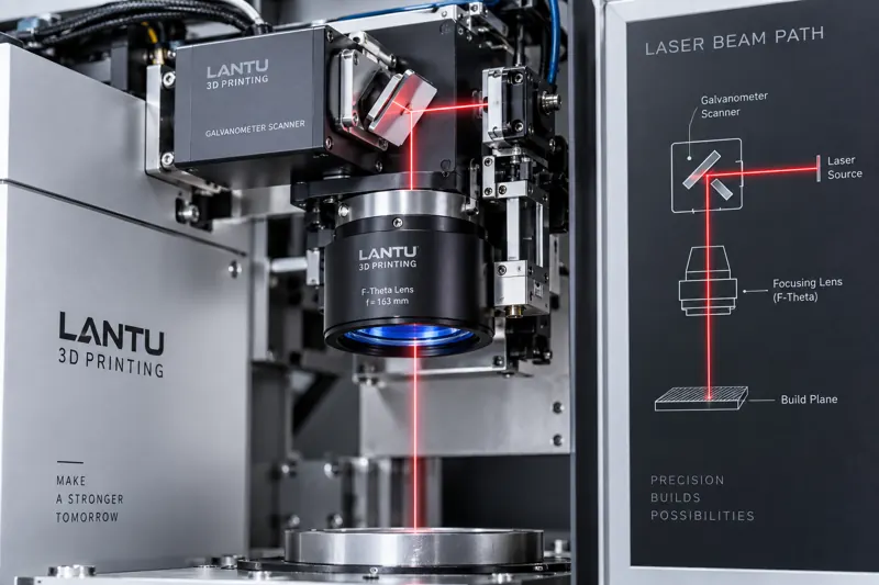
A typical fiber-laser SLM optical path consists of the fiber output end, collimating lens, X/Y galvanometer, F-theta focusing lens, and protective window. After collimation and focusing, a nominal 500 W fiber laser forms a beam spot of approximately 80 to 120 microns on the powder bed plane. A 10% change in beam spot diameter can change powder bed energy density by more than 20%. The galvanometer scans at 2,000 to 5,000 Hz, and angular deflection errors are linearly amplified into positional deviations, making them a primary source of contour distortion.
2. Effects of Optical Path Attenuation and Contamination
Protective windows and focusing lenses gradually become contaminated by spatter during long-term operation, reducing transmittance and lowering effective power. Dust can also cause scattering, leading to edge overheating. It is recommended to test transmittance every 500 to 1,000 printing hours or whenever switching to critical parts. If transmittance falls below 90% of the initial value, the optic should be replaced. For titanium and aluminum applications with severe spatter, the inspection interval should be shortened to every 250 hours.
3. Calibration Intervals for Galvanometers and Focus
Galvanometer calibration is performed by scanning a standard grid calibration plate and comparing it with the measured point cloud to correct nonlinear distortion. The target full-field positioning error should be within ±50 microns. The focus position, or Z focus, can shift due to thermal drift of the lens, so it should be verified weekly using a focus tester or thin-plate ablation method to ensure the focal point falls within ±0.1 mm of the powder bed surface. Laser power should be measured monthly with a thermal power meter. If deviation exceeds ±3%, the laser output curve must be recalibrated.
4. Daily Maintenance Checklist and Downtime Strategy
A tiered inspection system should be established: visually inspect the protective window and air curtain pressure every shift; clean optical windows and verify that the inert gas dew point is no higher than -40°C every week; perform power and galvanometer calibration every month. If blurred contours, rounded corners, or density fluctuations within the same layer are observed, the optical system should be checked first instead of blindly adjusting parameters. After maintenance, first-article confirmation using standard test coupons, such as step blocks or overhang angle tests, must be completed before production resumes.
Conclusion
The laser optical system is a fundamental variable that determines SLM consistency. By incorporating protective window transmittance, galvanometer positioning error, laser power, and focus position into regular calibration, and by using standard test coupons for first-article verification after maintenance, equipment condition can be transformed from an uncontrollable disturbance into a measurable and controlled factor, providing stable support for both small-batch and mass production delivery.
Submit a model, drawing, image or written notes. Engineers will review material, process, finishing and delivery based on actual use.