
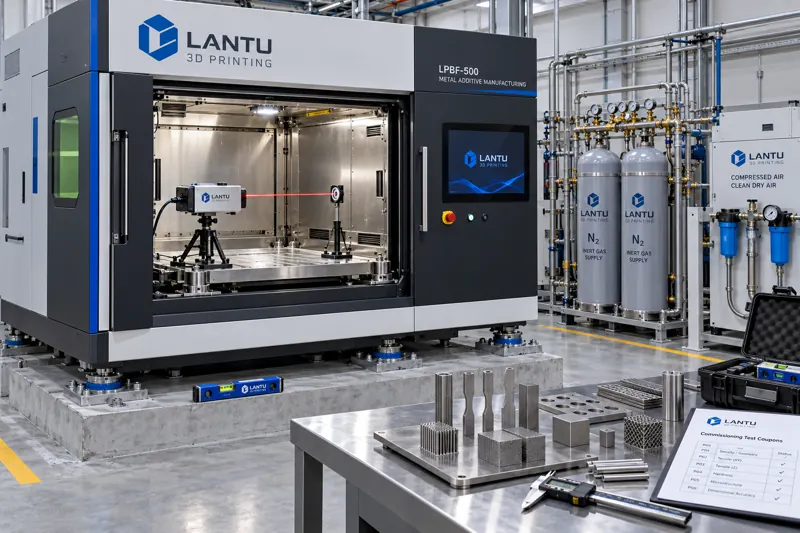
Introduction: Equipment Arrival Is the True Beginning of Risk
In many additive manufacturing projects, signing the purchase contract and receiving the equipment are regarded as key milestones, while subsequent installation and commissioning are often compressed into a minor task of “having the manufacturer send someone for two days.” Field failure data point to the opposite conclusion: a significant share of accuracy drift, powder-path blockages, substrate deformation, and other issues occurring during the first six months of metal 3D printer operation are not intrinsic machine defects. Instead, they stem from inadequate site conditions, gas quality, foundation load capacity, and handover verification during installation.
For platforms such as lantu3D, which assume full-lifecycle responsibility from design drawings to physical delivery, equipment is not an isolated processing unit; it is the first process parameter in the production chain. The engineering objective of equipment installation, commissioning, and Site Acceptance Testing (SAT) is clear: move the machine from “able to power on” to “able to consistently produce conforming parts,” while converting this process into a documented, reviewable, and traceable chain of evidence rather than a verbal confirmation.
1. Division of Responsibilities Between SAT and FAT: Do Not Treat Factory Inspection as a Site Conclusion
Factory Acceptance Testing (FAT) is performed at the manufacturer’s site and verifies the equipment’s functions and specifications: nominal laser power, galvanometer scanning range, recoating repeat positioning accuracy, build-cylinder lift resolution, oxygen concentration control, and gas recirculation and purification capability. FAT typically uses the manufacturer’s own power supply, gas supply, and standard powder, under controlled environmental conditions and with geometries familiar to the manufacturer.
SAT is fundamentally different: it is performed at the user’s site, using the user’s power grid and gas supply, the powder batch intended for actual production, and the real family of parts to be manufactured. The two cannot replace one another. An engineering rule should be clearly defined: FAT approval is a necessary condition for equipment release, while SAT approval is a sufficient condition for production launch. A common mistake is to archive the FAT report as the sole acceptance basis. As a result, variables such as onsite voltage fluctuation, compressed-air moisture content, and floor vibration remain unverified and emerge as quality incidents after production begins.
2. Site and Infrastructure: Five Critical Requirements Must Be Quantified
Equipment infrastructure requirements should be confirmed and documented before delivery, rather than remedied after the machine has been installed. At least five indicators must be quantified.
The first is foundation load capacity and levelness. For a typical four-laser metal LPBF system, the operating weight of the machine, including powder and cooling units, often reaches 2.5 to 4 tonnes. Static load capacity is typically required to be 800 to 1,200 kg/m², while levelness deviation of the installation surface must be controlled within 0.5 mm/m. Excessive deviation in levelness is directly transmitted to the relative position of the recoater blade and build plate, causing systematically thinner powder layers on one side of the build area.
The second is power quality. Lasers and galvanometers are sensitive to voltage transients. Engineering practice requires steady-state supply-voltage deviation to remain within ±10% of the rated value, with dedicated voltage stabilization or electrical isolation installed upstream of the equipment. For systems equipped with high-power heated build plates, inrush current must be separately considered when sizing circuit breakers. This prevents voltage drops caused by sharing circuits with other high-load workshop equipment.
The third is gas quality. Inert-gas supply affects more than oxygen concentration: the dew point and oil content of compressed air directly determine pneumatic-component service life and whether powder conveying lines become contaminated. Compressed air generally requires an atmospheric-pressure dew point no higher than -20 °C and an oil content below 0.1 mg/m³, with three-stage filtration and automatic condensate drainage at the equipment inlet. This requirement is among the most frequently overlooked onsite and is also likely to surface six months later as sticking pneumatic cylinders.
The fourth is ambient temperature, humidity, and vibration. Thermal equilibrium inside the build chamber depends on stable ambient temperature, generally controlled at 22±3 °C with relative humidity below 60%. Where nearby stamping presses, frequent forklift traffic, or floor-mounted air compressors are present, vibration should be measured in the field to prevent periodic disturbances from entering the melt-pool solidification process.
The fifth is emissions control and safety provisions. Metal-powder handling areas require dedicated dust extraction and explosion-protected electrical configurations. Waste-powder collection containers must be equipotentially bonded to ground, while inert-gas piping requires leak detection and alarms for oxygen concentration in the surrounding space. These are baseline safety-compliance requirements and must be listed separately in the SAT checklist; acceptance based on a promise to “complete them later” is not acceptable.
3. Technical Focus of Installation and Commissioning: From Geometric to Process Baselines
The first technical focus during installation is establishment of the geometric baseline. After positioning the equipment, the following steps should be completed in sequence: leveling the machine base; correcting the parallelism between the build cylinder and build-plate plane; calibrating the gap between the recoater blade or roller and the build plate; and aligning the galvanometer coordinate system with the build platform. Recoater-gap calibration typically requires accuracy in the range of 0.02 to 0.05 mm and must be measured at multiple points across the build area rather than verified at a single point.
The second focus is establishment of the process baseline. A compliant geometric baseline only demonstrates that the machine has been “installed correctly”; the process baseline demonstrates that it “prints well.” During commissioning, a set of standard test specimens should be produced covering three types of features: dimensional features, such as stepped blocks and cylindrical hole patterns, for calibrating shrinkage compensation factors; surface features, such as inclined surfaces at different angles, for confirming the relationship between surface quality and inclination angle; and structural features, such as thin walls, overhangs, and lattice units, for confirming process limits.
Measurement results for the standard specimens must be compiled into a baseline data file for comparison during subsequent periodic verification. Without a baseline, it is impossible to determine whether an out-of-tolerance dimension detected three months later is due to equipment deterioration or process drift.
4. SAT Acceptance Checklist: Breaking Down “Usable” into Verifiable Items
An executable SAT checklist should contain four categories of acceptance criteria. Safety items are mandatory pass/fail gates: grounding resistance, explosion-protection configuration, oxygen monitoring, emergency-stop circuits, and laser interlocks. Failure of any item prohibits entry into the next stage. Functional items should be verified individually, including recoating cycles, atmosphere purging, build-plate heating uniformity, filter backflushing, and software-hardware version compatibility. Accuracy items should be determined using measured data, including critical dimensional deviations of standard test specimens, surface roughness, and density-section results; specific thresholds and measurement methods must be defined. Documentation items confirm completeness of delivery, including operating manuals, maintenance manuals, electrical and gas-circuit drawings, spare-parts lists, calibration certificates, and FAT reports.
Acceptance criteria must be specified in advance in contract appendices or the acceptance plan to avoid ad hoc onsite negotiation. Engineering experience shows that most acceptance disputes are not technical disagreements, but rather result from failing to agree in advance on evaluation methods and tolerance definitions.
5. Trial Operation and Production Release: From Standard Parts to Real Orders
Passing SAT does not mean the equipment is ready to accept formal production orders. A sound approach is to arrange a productive trial-operation period, typically two to four weeks, during which representative parts from real customer orders are used for validation. Three categories of data should be recorded: first-batch yield, equipment availability, defined as actual printing time as a proportion of planned time, and the number and categorized causes of unplanned shutdowns.
Recommended production-release criteria should be quantified as follows: a first-pass yield for three consecutive batches of representative parts no lower than the defined target, for example 95%; equipment availability of no less than 85%; and no unplanned hardware replacements. Once these criteria are met, a production-release document should be signed to transition the equipment from “commissioning status” to “production status.” The current process parameter package should simultaneously be frozen as the baseline for future changes. Any parameter change should follow change-control procedures and require retesting of standard specimens to prevent unnoticed accumulation of parameter drift.
6. Common Pitfalls and Countermeasures
The first category is “production before acceptance is complete.” Under pressure to fulfill orders, work is assigned to equipment before SAT is completed. If quality issues arise, responsibility boundaries become unclear and it is impossible to distinguish among equipment-, material-, and process-related causes. The countermeasure is to make SAT completion a mandatory prerequisite for releasing the equipment in the order-management system, with a hard process-level block.
The second category is “baseline data not retained.” Measurement values from standard specimens produced during commissioning are not archived, making later accuracy disputes impossible to trace. The countermeasure is to establish a baseline record for every machine, including specimen identification numbers, measurement reports, the process parameter package used at the time, and environmental-condition records.
The third category is “infrastructure delivered to minimum standards.” Gas and power supplies are accepted merely because the equipment can start, resulting in continued degradation during operation. The countermeasure is to define in SAT a periodic reinspection interval for these indicators, such as quarterly checks of compressed-air dew point and power-supply voltage fluctuation records.
Conclusion
The value of equipment installation, commissioning, and Site Acceptance Testing is not the addition of another signed document; it is the early identification and control of uncertainty. The five critical site requirements, the establishment of dual geometric and process baselines, a checklist structured around four categories of acceptance criteria, and trial-operation release using real orders together form an engineering pathway from “equipment delivered” to “stable production output.” For platforms responsible for full-lifecycle delivery, this pathway, subsequent quality traceability, capacity planning, and maintenance systems are different dimensions of the same data foundation: the more complete the baseline created during installation, the faster and more accurate later deviation assessment will be.
Submit a model, drawing, image or written notes. Engineers will review material, process, finishing and delivery based on actual use.