
Introduction: Why Parameter Optimization Keeps Going in Circles
In on-site commissioning of metal laser powder bed fusion (LPBF) and polymer sintering processes, a common scenario is this: an engineer increases laser power from 250 W to 280 W, density rises by 0.3%, so the power is increased further; at 300 W, keyholing occurs, and the setting must be reduced again. After more than a dozen specimens, the result is a fragmented empirical curve that must be recreated when changing machines or powder batches. The issue is not a lack of effort; rather, the one-factor-at-a-time method cannot address interactions. Power and scan speed jointly determine volumetric energy density, while powder layer thickness changes melt-pool heat dissipation conditions. These three factors are coupled, and changing only one variable at a time can never reveal the full picture.
Design of Experiments (DoE) provides an engineering path for solving such multi-factor coupling problems: using the fewest possible specimens to estimate main effects, interaction effects, and response surfaces in a single effort, while defining releasable process windows with confidence intervals. For 3D printing process development, this article presents a complete, actionable method from orthogonal screening and response surface modeling to window validation.
I. First Distinguish the Three Types of Experiments: Screening, Modeling, and Validation
Process development cannot be completed with a single experiment. It generally proceeds through three tiers, each with different objectives, factor counts, and specimen quantities.
The first tier is screening experiments, intended to identify the truly significant 2–4 factors from 6–10 candidate factors. Typical candidates include laser power, scan speed, hatch spacing, layer thickness, preheat temperature, scan strategy (stripe width), interlayer rotation angle, and shielding-gas flow rate. Partial factorial or Plackett-Burman designs are used in the screening stage, which can be completed in 8–12 runs, with density and surface roughness as the two coarse response indicators.
The second tier is modeling experiments, intended to establish a response surface model for the 2–3 key factors identified during screening. Central composite design (CCD) or Box-Behnken design is commonly used. A three-factor CCD includes 6 axial points, 8 factorial points, and 6 center-point replicates, for a total of 20 runs. The responses are expanded to include density, tensile strength, dimensional deviation, and surface roughness Ra.
The third tier is validation experiments, in which 3–5 confirmation points within the model-predicted optimum region are printed repeatedly to determine whether the deviation between predicted and measured values remains within ±5%. Once validation is passed, the window boundaries are tightened by 10% to define the parameter range on the production process card.
II. Orthogonal Experiments: Covering the Largest Space with the Fewest Specimens
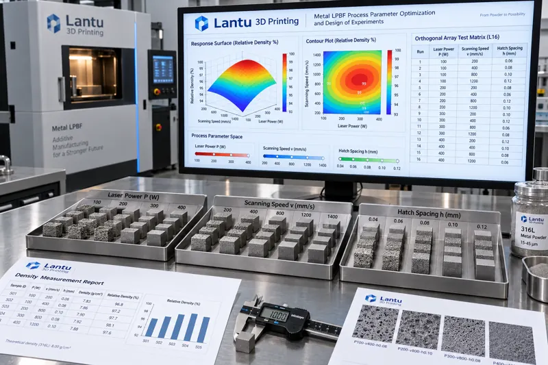
When the number of factors is limited and all factors have the same number of levels, an orthogonal array is the most economical choice. Taking 316L stainless steel LPBF as an example, consider three factors at three levels: laser power P, scan speed v, and hatch spacing h. A full factorial design requires 27 runs, whereas an L9(3^4) orthogonal array requires only 9.
The specific design uses P at 200/240/280 W, v at 800/1000/1200 mm/s, and h at 0.09/0.11/0.13 mm. Following the L9 arrangement, a set of 10×10×10 mm cubic specimens is printed for each factor combination. Density is measured using the Archimedes method, while surface roughness Ra is also recorded.
Range analysis can be used for rapid ranking: calculate the mean response of each factor at each level, where the range R = max(mean response) − min(mean response). A larger R indicates a more significant factor effect. If R(P)=2.1%, R(v)=1.4%, and R(h)=0.6%, the order of importance is power > speed > spacing. Analysis of variance (ANOVA) is then performed to determine significance using the F-test: factors with F values above the critical value and p values below 0.05 proceed to the next modeling stage.
The limitation of orthogonal experiments is that they assume no interactions among factors. If strong coupling between power and speed is suspected—because volumetric energy density E = P/(v·h·t) is itself a multiplicative relationship—response surface design should be used during the modeling stage rather than forcing a continued orthogonal-array approach.
III. Response Surface Methodology: From Discrete Points to Continuous Surfaces
The core of response surface methodology (RSM) is fitting the relationship between responses and factors with a quadratic polynomial:
Y = β0 + Σβi·xi + Σβii·xi² + Σβij·xi·xj + ε
Here, the cross term βij quantitatively represents the interaction effect. In a CCD, the key parameter for a three-factor plan is the axial distance α. For a rotatable design, α = 2^(k/4) = 2^(3/4) ≈ 1.682, where k is the number of factors. Axial points are located at ±1.682 in coded space, factorial points at ±1, and center points are replicated six times to estimate pure error.
After fitting, three tests are essential. First is the lack-of-fit test: a p value greater than 0.05 indicates no significant discrepancy between the model form and the data. Second are the coefficient of determination R² and adjusted R²; their difference should be less than 0.2, otherwise overfitting may be present. Third are checks for residual normality and homoscedasticity. A common situation in practice is an R² of 0.95 but an adjusted R² of only 0.86; in this case, the model should be refitted after removing insignificant cubic terms.
Multi-response optimization is a challenge in 3D printing: density must be maximized, roughness minimized, and dimensional deviation brought as close to zero as possible, while these objectives often conflict. In engineering practice, a desirability function maps each response to a 0–1 scale, after which a geometric mean is calculated to obtain the overall desirability D. The parameter combination is determined at the maximum D. Weights are assigned according to customer acceptance priorities; for example, aerospace parts may assign weights of 0.5 to density, 0.3 to roughness, and 0.2 to dimensional deviation.
IV. Process Window Qualification: Turning an Optimum Point into a Releasable Range
Finding the optimum point is only the first step; production requires a range. A practical method is the overlay contour plot: plot contour lines for the acceptance thresholds of each response—density ≥ 99.5%, Ra ≤ 12 μm, and dimensional deviation ≤ ±0.1 mm—and use the overlap of all contour regions as the process window.
A safety margin must be retained after the window is defined. The recommended practice is to shrink the window boundaries inward by 10%. For example, if the model gives a feasible power range of 235–265 W, the process card should specify 238–262 W. This is because powder batch variation, shielding-gas purity drift, and optical-system power attenuation can gradually shift the actual process point. Maintaining margin can raise the process capability index Cpk from 1.0 to above 1.33.
Window validation uses confirmation across three batches: print five parts per batch at the window center, just inside the upper boundary, and just inside the lower boundary. If all three consecutive batches pass and the drift in batch means is less than one-third of the response standard deviation, the window can be considered stable. The validation data should also be entered into the process log as a baseline for future traceability.
V. Common Pitfalls and an Execution Checklist
Pitfall 1: Treating specimen quantity as the entirety of cost. In reality, 9 orthogonal runs plus 20 CCD runs cost far less than 30 blind one-factor-at-a-time iterations, while producing a reusable model.
Pitfall 2: Ignoring block effects. If 20 CCD runs are completed over three days, changes in machine condition, powder batch, and environmental temperature and humidity can be mixed into the residuals. The correct approach is to include date as a blocking factor in the design, or arrange center-point replicates within blocks to monitor drift.
Pitfall 3: Looking only at density. A process point with 99.5% density may not necessarily meet mechanical-property requirements, because lack-of-fusion defects can be underestimated by density measurements. At minimum, tensile strength and elongation should be tested concurrently; metallography and industrial CT spot inspections should be added when necessary.
Execution checklist: Do factor levels cover the range in which the equipment can operate stably? Are center-point replicates included to estimate pure error? Has a lack-of-fit test been conducted? Are multi-response weights consistent with customer acceptance criteria? Does the window retain a 10% margin? Do validation batches cover the window boundaries?
Conclusion
Design of Experiments transforms 3D printing process development from empirical trial and error into a quantifiable, repeatable engineering activity: orthogonal experiments complete factor screening in 9–12 runs; response surface methodology uses approximately 20 runs to establish quadratic models incorporating interaction effects; desirability functions resolve multi-objective conflicts; and overlay contour plots define releasable process windows with safety margins. For full-lifecycle management platforms such as lantu3D, which support the entire journey from blueprint design to physical delivery, the value of DoE extends beyond parameter tuning—it captures process knowledge as searchable, reusable, and verifiable parameter models, making every process development effort the starting point for the next rather than another restart from zero.
Submit a model, drawing, image or written notes. Engineers will review material, process, finishing and delivery based on actual use.