
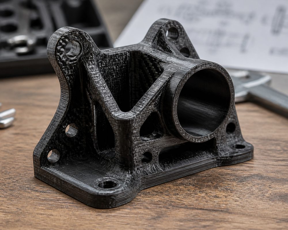
Principle of Continuous Fiber Reinforcement Technology
Continuous fiber reinforced 3D printing technology represents a significant technological breakthrough in the field of additive manufacturing. Unlike the composites filled with chopped fibers used in traditional 3D printing (where fiber lengths are merely 0.2–0.5 mm), continuous fiber reinforcement technology enables the embedding of continuous carbon, glass, or aramid fibers into a thermoplastic matrix (such as Nylon, PETG, or PEEK) during the printing process, forming a structure similar to traditional composite laminates. This structure allows printed parts to achieve metal-level tensile strength while weighing only 1/5 to 1/3 that of metal.
Currently, there are primarily two technical routes on the market. One is the "dual-nozzle" technology pioneered by Markforged, where one nozzle prints the matrix material (such as Onyx, i.e., chopped carbon fiber filled nylon), while the other simultaneously lays down continuous fiber. The other is the "composite fiber co-extrusion" technology proposed by Anisoprint, which pre-combines continuous fiber with the matrix material inside the print head before extruding them simultaneously. Both technologies have their respective advantages: the former offers greater flexibility in controlling fiber volume fraction, while the latter excels in complex fiber path planning.
Material Systems and Performance Comparison
The fiber materials available for continuous fiber reinforced 3D printing primarily include carbon fiber, glass fiber, and aramid fiber (such as Kevlar). Carbon fiber possesses the highest specific strength (strength-to-density ratio) and specific modulus, making it the preferred choice for lightweight applications; however, its electrical conductivity and high cost are also factors that need to be considered. Glass fiber features lower cost and good electrical insulation properties, but its strength and modulus are lower than those of carbon fiber. Aramid fiber has extremely high toughness and impact resistance, and is commonly used in special applications such as bulletproofing and protection.
The selection of matrix materials is equally critical. Nylon (PA6, PA12) is the most commonly used matrix material, offering excellent interlayer bonding strength and chemical stability. When PETG serves as the matrix, printing becomes easier, but its temperature resistance is relatively poor. PEEK, as a high-performance matrix, can withstand operating temperatures above 250°C, making it suitable for extreme environments such as aerospace and oil drilling; however, its printing difficulty and cost are correspondingly higher. The tensile strength of typical carbon fiber/nylon composites can reach 700-900 MPa, with an elastic modulus of approximately 60-80 GPa, far surpassing that of aluminum alloys.
Design Method and Fiber Path Planning
The design methodology for continuous fiber reinforced printing differs fundamentally from that of traditional 3D printing. In traditional 3D printing, designers primarily focus on geometric shape and dimensional accuracy; whereas in continuous fiber printing, the fiber layup direction and path planning directly determine the mechanical properties of the part. According to the fundamental principles of composite mechanics, fibers provide the optimal reinforcement effect in the direction of the applied load, while the reinforcement effect is limited in the direction perpendicular to the fibers. Therefore, designers need to predict the primary load direction of the part and plan the fiber paths accordingly.
Modern slicing software (such as Eiger, Cura with composite plugin) offers various fiber routing modes. Unidirectional routing is suitable for parts primarily subjected to unidirectional loads; cross-ply routing (0°/90° or ±45°) is suitable for parts subjected to multi-directional loads; and concentric routing is suitable for tubular parts, providing reinforcement in the hoop direction. For complex parts, Finite Element Analysis (FEA) can be used to optimize fiber routing schemes, increasing fiber density in stress concentration areas while reducing fiber usage in non-critical areas to lower costs.
Process Parameter Optimization
Process parameter optimization for continuous fiber printing is more complex than for traditional 3D printing. First is the control of Fiber Volume Fraction (FVF); the higher the FVF, the higher the part strength, but the greater the printing difficulty. It is generally recommended to control the FVF between 20% and 40%, as an excessively high FVF leads to poor fiber impregnation and reduced interlayer bonding strength. Second is fiber tension control; appropriate tension can ensure that fibers remain straight within the matrix, avoiding buckling and wrinkling; however, excessive tension may lead to fiber breakage or insufficient extrusion of the matrix material.
Printing temperature significantly affects the bonding quality between the fiber and the matrix. Taking carbon fiber/nylon as an example, the printing temperature typically needs to be set between 260-280°C to ensure the nylon is fully melted and wets the fiber surface. It is recommended to control the layer thickness between 0.2-0.3mm; a layer that is too thin will result in over-compression of the fiber, while a layer that is too thick will affect the positioning accuracy of the fiber. Furthermore, the printing speed should be appropriately reduced, typically not exceeding 30-50mm/s, to ensure the fiber is properly laid.
Analysis of Typical Application Scenarios
Continuous fiber reinforced 3D printing demonstrates immense application value across various sectors. In the aerospace industry, this technology is employed to manufacture lightweight components such as UAV fuselage frames, satellite brackets, and rocket engine nozzles. Due to the complex geometries and small batch sizes of these components, traditional manufacturing methods (such as manual composite lay-up) are costly, whereas continuous fiber 3D printing can significantly reduce costs while ensuring performance. In the automotive industry, this technology is utilized to manufacture racing car chassis components, intake manifolds, and suspension components, enhancing vehicle performance through lightweighting.
In the field of industrial manufacturing, continuous fiber printing is an ideal choice for producing high-performance tooling and fixtures. Traditional metal fixtures are heavy and have long manufacturing cycles, whereas continuous fiber fixtures are lightweight, high-strength, and rapid to manufacture, which can significantly improve production efficiency. In the field of medical devices, carbon fiber composites are used to manufacture surgical guides, rehabilitation braces, and other medical equipment due to their excellent X-ray transparency and biocompatibility. Furthermore, in the sporting goods sector, this technology is also used to manufacture high-performance bicycle frames, skis, fishing rods, and other products.
Quality Inspection and Performance Evaluation
Quality inspection of continuous fiber-reinforced 3D printed parts is more complex than that of traditional parts. In addition to routine dimensional inspection and visual examination, attention must also be paid to fiber distribution uniformity, the bonding quality between fibers and the matrix, and internal defects (such as fiber waviness, voids, and unwetted areas). Industrial CT scanning is currently the most effective non-destructive testing method, capable of clearly revealing the three-dimensional distribution of fibers and internal defects. Ultrasonic testing can also be used to inspect interlayer bonding quality and fiber continuity.
Mechanical property testing is a direct method for evaluating print quality. In addition to standard tensile, flexural, and compression tests, attention must also be paid to Interlaminar Shear Strength (ILSS), which is the weakest link in composite materials. For critical applications, fatigue testing and impact testing are also required to evaluate the performance of parts under dynamic loads. It is worth noting that the mechanical properties of continuous fiber printed parts exhibit significant anisotropy; therefore, the relationship between the loading direction and the fiber direction must be clearly defined during testing.
Technical Challenges and Development Trends
Despite the significant progress made in continuous fiber reinforced 3D printing technology, it still faces several technical challenges. First is the limitation of print size; currently, the build size of most continuous fiber printers falls within the 300-600mm range, making it difficult to meet the manufacturing demands of large structural components. Second is material cost; the price of continuous fibers (especially carbon fiber) remains relatively high, limiting the widespread adoption of this technology. Third is the maturity of design software; currently, most slicing software remains relatively rudimentary in terms of fiber path planning and lacks deep integration with CAD/CAE software.
Future development trends primarily include: 1) breakthroughs in large-scale printing technology, enabling the fabrication of large parts through multi-axis robotic arms or gantry structures; 2) the development of novel fiber materials, such as basalt fibers and natural fibers as low-cost alternative materials; 3) intelligent fiber placement technology, achieving more precise fiber control through real-time monitoring of fiber tension and position; and 4) integration with AI technology, utilizing machine learning algorithms to automatically optimize fiber placement schemes and lower the design threshold. As these technologies mature, continuous fiber reinforced 3D printing is poised to become one of the mainstream technologies for lightweight manufacturing.
Submit a model, drawing, image or written notes. Engineers will review material, process, finishing and delivery based on actual use.