
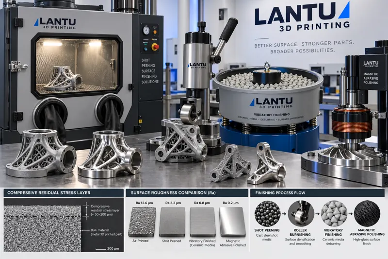
1. Additively Manufactured Parts Cannot Stop at the As-Built Surface
The surface of a metal AM part removed from the machine is the result of overlapping melt tracks, adhered partially melted particles, and stair-step effects. In laser powder bed fusion (LPBF), for example, sidewall roughness commonly ranges from Ra 8 to 20 μm, while downward-facing surfaces with severe powder adhesion can exceed 25 μm. By comparison, the same part can be consistently machined to an Ra below 1.6 μm. This gap is not merely cosmetic: with each increase in roughness grade, fatigue crack initiation becomes more concentrated at the valleys of interlayer overlap and at the roots of adhered particles.
In bench testing of a Ti6Al4V conformal-cooling insert, the rotating-bending fatigue limit of as-built specimens was approximately 45% to 55% of that of wrought base material. Sandblasting followed by electropolishing raised this value to roughly 70%; adding shot peening to introduce a residual compressive stress layer restored it to more than 85%. Post-lavorazione is therefore not a final cosmetic step, but a critical operation that determines whether a part can enter load-bearing service.
2. Four Metrics for Evaluating Surface Integrity
Before discussing mechanical strengthening and finishing, measurement criteria must be standardized. Four metrics are commonly used to describe surface integrity: first, profile roughness Ra and Rz, which describe the amplitude of microscopic surface variations; second, residual stress in the surface layer, where compressive stress helps suppress crack opening and tensile stress has the opposite effect; third, surface microhardness and work-hardened layer depth, which reflect the extent of plastic deformation; and fourth, edge condition, including burr height, edge radius, and consistency.
These four factors constrain one another. Aggressive chemical polishing intended solely to achieve low Ra may remove the compressive stress layer produced by shot peening. Shot peening without smoothing introduces compressive stress, but surface valleys remain crack initiation sites. Process routes must therefore be prioritized by metric: first identify the main driver of the failure mode, then determine the sequence of strengthening and smoothing operations.
3. Shot Peening and Shot Blasting: Introducing a Residual Compressive Stress Layer
Shot peening is the most mature mechanical strengthening method. Cast-steel or ceramic media propelled by compressed air at 40 to 80 m/s strike the surface, causing plastic deformation in the surface layer. The layer is forced to expand laterally but is constrained by the elastic substrate beneath it, thereby creating residual compressive stress. Typical parameters include cast-steel shot diameters of 0.2 to 0.6 mm, coverage requirements of 100% to 200%, and Almen intensity controlled at 0.15 to 0.35 mmA, with titanium alloys generally using the upper range and aluminum alloys the lower range. Peak residual compressive stress typically occurs 50 to 150 μm below the surface and can reach 50% to 60% of the material's yield strength.
Two considerations are particularly important for AM parts. First, partially melted particles on as-built surfaces may detach during shot peening and leave small pits. A light sandblasting or vibratory finishing step is therefore recommended before peening to remove loosely adhered material. Second, inadequate coverage creates untreated strengthening blind spots and may instead cause localized stress discontinuities. Coverage should be confirmed using both Almen strips and coverage inspection media, rather than estimated from treatment time alone.
4. Burnishing and Laser Shock Peening: Deeper Strengthened Layers
When part geometry is regular, such as rotational components, flat surfaces, or uniform bore walls, burnishing provides greater consistency than shot peening. A hydraulic or mechanical burnishing tool rolls across the surface with an indentation depth of 0.1 to 0.3 mm and a feed rate of 0.05 to 0.15 mm/rev. It can achieve Ra values below 0.4 μm while creating a compressive stress layer 200 to 500 μm deep. Because it also improves surface roughness, burnishing combines strengthening and smoothing in a single operation.
Laser shock peening (LSP) is intended for thin walls and complex profiles. Short-pulse laser energy generates gigapascal-level shock waves through an absorptive layer and a confinement layer, producing a compressive stress layer more than 1 mm deep with minimal thermal impact. The trade-off is equipment cost and cycle time: with a spot size of 3 to 5 mm, covering a 100 cm² profile requires thousands of pulses. It is better suited to high-value parts such as aircraft blade roots and thin-walled structural frames than to high-volume small components.
5. Vibratory Finishing and Magnetic Abrasive Finishing: Smoothing Internal Channels
Conformal cooling channels, lattice structures, and intersecting internal holes are regions that conventional abrasive tools cannot reach, and they are often the areas with the poorest AM surface quality. Vibratory finishing immerses the part in abrasive media, such as ceramic, plastic, or steel media. Vessel vibration creates relative sliding that performs uniform, low-level abrasion on all exposed surfaces. A single treatment of 2 to 8 hours can reduce Ra from 15 μm to 3 to 5 μm. Media size and shape must be selected according to the minimum channel cross-section, typically at one-fifth to one-eighth of the channel diameter, to prevent media entrapment.
Magnetic abrasive finishing is better suited to precision internal cavities. Driven by a rotating magnetic field, magnetic abrasive media form a flexible abrasive brush along complex surfaces. It can produce a mirror-like finish below Ra 0.8 μm in stainless-steel and titanium-alloy internal flow channels without leaving tool marks or altering cross-sectional dimensions as rigid tools may do. Its limitation is that abrasive force on non-ferromagnetic materials depends heavily on magnetic-field design; smoothing efficiency for aluminum and copper alloys is significantly lower than for steel.
6. Deburring and Edge Conditioning
The final obstacle to assembly consistency is often the edge condition. Common burr sources in AM parts include residual stubs after support removal, nodular protrusions formed by sintered powder adhesion, and interlayer steps at threads or hole entrances. Manual filing offers the poorest consistency: chamfer dimensions can vary by more than 0.3 mm between operators within the same production batch, directly causing variation in assembly torque.
A controlled approach is to establish edge specifications. Drawings should define allowable burr height, such as no more than 0.1 mm, and an edge-radius range, such as R0.2 to R0.5. Standardized abrasive-flow processes, nylon brushes, or compact barrel-finishing equipment can then be used, followed by sampling inspection with the same measurement system. Converting edge condition from a matter of experience into a measurable requirement can typically reduce rework rates by more than half.
7. Process Route Selection and Validation
Process routes can be developed backward from the failure mode. For fatigue-dominated load-bearing parts, use smoothing before strengthening: sandblasting to remove adhered material → vibratory finishing or electrolytic smoothing → shot peening or burnishing to introduce compressive stress → cleaning and passivation. For sealing- or fluid-performance-dominated parts, prioritize smoothing and minimize strengthening steps to prevent the compressive stress layer from being worn away during subsequent assembly. For cosmetic parts, target texture consistency by controlling abrasive-media batches and processing time.
Validation also requires a closed loop. It is recommended to retain one set of witness specimens from each batch for surface-roughness sampling, residual-stress sampling by X-ray diffraction, and first-article fatigue or crush testing. The data should then be fed back into the process documentation. Without these measurements, a supposedly qualified post-processing procedure remains only an empirical description and may fail when equipment or production shifts change.
Conclusion
Mechanical surface strengthening and finishing address one of the most underestimated issues in additive manufacturing: surface valleys, adhered particles, and residual tensile stress on as-built surfaces. In engineering practice, the four surface-integrity metrics should be prioritized, the primary failure driver identified, and shot peening, burnishing, laser shock peening, vibratory finishing, and magnetic abrasive finishing combined accordingly. Edge specifications and sampling data should also be documented in process instructions. For an end-to-end management platform such as lantu3D, supporting delivery from digital design to physical parts, post-processing parameters and validation records are equally reusable assets: they determine whether an as-built printed blank can truly become a deliverable, traceable engineering component.
Invia un modello, un disegno, un'immagine o note scritte. Gli ingegneri valuteranno materiale, processo, finitura e consegna in base all'uso effettivo.