
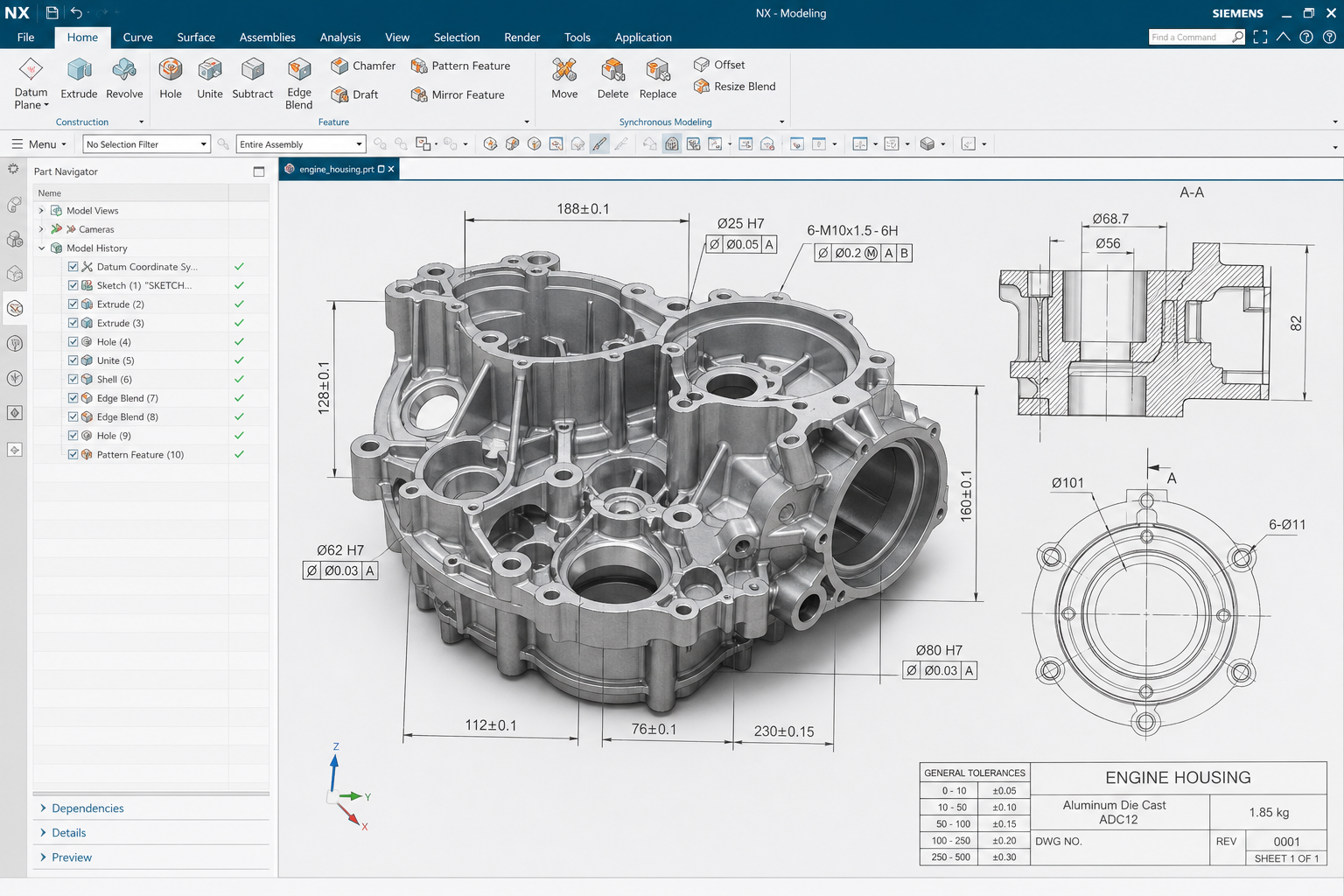
Theoretical basis of wall thickness gradient design
Wall thickness gradient design refers to a structural design method that distributes different thicknesses in the same part according to load-bearing requirements. In traditional designs, the wall thickness of parts is usually kept uniform. Although this approach is simple in design, it often results in wasted material and redundant weight. Wall thickness gradient design is based on mechanical analysis, increasing wall thickness in critical load-bearing areas and reducing wall thickness in low-stress areas to achieve optimal distribution of materials. This design concept is connected with the principles of bionics, and many biological structures (such as bones and bamboo) adopt similar material distribution strategies.
Load-loading analysis and wall thickness distribution planning
To carry out wall thickness gradient design, you first need to perform load-bearing analysis on the parts. Finite element analysis (FEA) is used to determine the stress distribution of parts under operating loads and identify high-stress and low-stress areas. The wall thickness design in high stress areas needs to ensure that the stress level is lower than the allowable stress of the material, and the minimum wall thickness is determined after considering the safety factor. The wall thickness of the low stress area can be reduced to the minimum allowed by the process, usually 0.8-1.5mm. The wall thickness change in the transition zone needs to be gentle to avoid stress concentration. The direction of the wall thickness gradient should be consistent with the load transfer path, allowing for more efficient material placement.
Constraints of 3D printing process on wall thickness design
Wall thickness design needs to consider the limitations of 3D printing process. The minimum wall thickness depends on the process accuracy. The minimum wall thickness of the FDM process is usually 1-2 times the nozzle diameter (0.4-0.8mm), the SLA process can reach 0.4mm, and the SLM metal process is recommended to be no less than 0.5mm. The maximum wall thickness is affected by heat dissipation and stress. An overly thick solid structure will cause heat accumulation and increase internal stress. It is recommended that the thick-walled area be designed as a hollow structure with reinforced ribs. The wall thickness change rate should not be too large, and it is recommended not to exceed a change of 10% per millimeter to avoid defects in the transition zone. The wall thickness of the suspended area needs to consider its self-supporting ability. Overly thick suspended walls are prone to sagging.
Case study of wall thickness gradient design of typical parts
Take the drone fuselage frame as an example to illustrate the application of wall thickness gradient design. The fuselage frame bears the motor thrust and landing impact, with the greatest stress at the mounting points and connections. During design, the wall thickness in the motor mounting area is set to 3mm to ensure sufficient strength and rigidity. The stress in the middle of the frame is smaller and the wall thickness is reduced to 1.5mm. The stress in the connecting rib area is lower and the wall thickness is 1mm. With this design, the frame weight is reduced by 25% compared to a uniform wall thickness design, while the maximum stress remains within a safe range. When printing, the filling density is selected according to the wall thickness gradient, with 100% filling in thick-walled areas and 50% filling in thin-walled areas to further reduce weight.
Verification and optimization of wall thickness gradient design
After the wall thickness gradient design is completed, verification and optimization are required. The first is simulation verification. Finite element analysis is used to calculate the stress distribution under the design load and confirm the maximum stress location and value. The second step is print verification, where actual printed samples are measured for size and weight inspection. The third is functional verification, where the sample is loaded and tested to measure the deformation and failure load. Conduct design iterations based on test results to adjust wall thickness distribution. For complex parts, topology optimization software can be used to automatically generate wall thickness gradient distribution plans to improve design efficiency.
Submit a model, drawing, image or written notes. Engineers will review material, process, finishing and delivery based on actual use.