
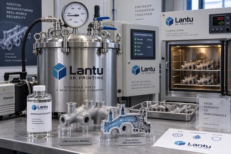
Introduction: Invisible Pores, Visible Failures
The most common reason for rework in pressure testing of metal 3D-printed parts is often not dimensional out-of-tolerance, but “leakage.” An SLM-formed aluminum alloy manifold may have an intact appearance, qualified dimensions, and a surface roughness reaching Ra 3.2 μm, yet fail to hold pressure adequately during a 0.6 MPa airtightness test. Sectioning analysis reveals a large number of interconnected pores inside. These are formed by gas entrainment during powder melting, keyhole collapse, and interlayer lack of fusion. Each individual pore may be only tens of micrometers in volume, but together they connect into leakage channels penetrating the wall thickness.
This type of problem is especially fatal in parts such as thin-walled cavities, hydraulic valve bodies, vacuum chambers, and heat-exchanger flow channels. Hot isostatic pressing (HIP) can close internal closed pores, but has limited effect on open pores connected to the surface. Adjusting process parameters to improve density sacrifices printing efficiency and dimensional stability. Vacuum impregnation / infiltration sealing has therefore become the most economical engineering reinforcement process in this gap: it does not change the part geometry, but fills the pores with a low-viscosity impregnant and cures it, completely blocking the interconnected channels.
1. Process Principles and Application Boundaries of Vacuum Impregnation
The physical process of vacuum impregnation can be divided into three stages. The first stage is vacuum degassing: the part is placed in a sealed tank, evacuated to an absolute pressure below 50–100 Pa, and held for 15–30 minutes so that air inside the pores expands and escapes, while moisture adsorbed on the pore walls is also removed. The second stage is impregnant infiltration: the impregnant is introduced under maintained vacuum or pressure after vacuum release, entering the pores under capillary action and pressure differential. Typical infiltration pressure is 0.4–0.8 MPa, with a holding time of 10–30 minutes, depending on wall thickness and pore scale. The third stage is curing and sealing: depending on the impregnant system, hot-water curing at 80–90 ℃ for 10–20 minutes or hot-air/oven curing at 120–180 ℃ for 30–60 minutes is used.
The key parameters are the viscosity and curing shrinkage of the impregnant. Methacrylate impregnants used industrially for metal castings typically have a viscosity of 10–30 mPa·s at 25 ℃ and can penetrate pores on the order of 10–50 μm. For finer pores in additive-manufactured parts, a dedicated low-viscosity (<10 mPa·s), low-shrinkage (volumetric shrinkage <3%) formulation is required. After curing, the impregnant should form an insoluble and infusible thermoset polymer, with a long-term service temperature range from -50 ℃ to 200 ℃ and short-term capability up to 250 ℃.
The application boundaries must be made clear: vacuum impregnation solves “sealing,” not “strength.” It can reduce leakage rates below the detection limit, but it offers limited improvement in fatigue performance, because the filler is a polymer rather than metal and cannot bear the primary load. If the part’s failure mode is high-cycle fatigue, HIP pore closure, optimized scanning strategies, and surface strengthening should remain the main measures, with impregnation used only as a sealing supplement. In addition, the impregnant cannot enter fully closed internal pores, so it is ineffective for isolated internal voids.
2. Process Flow Design and Key Control Points
A reproducible impregnation production line should include six stations: pre-treatment cleaning, drying, fixturing and tank loading, vacuum impregnation, centrifugal/residual rinsing, and curing plus inspection. Each station must have clear control indicators.
The goal of pre-treatment is to make the pores “clean and dry.” Residual powder on additive-manufactured part surfaces, burrs from support breakage, and cutting fluids can block pore openings and directly cause impregnation failure. The recommended process is: alkaline cleaning at 50–60 ℃ for 5–10 minutes → deionized-water rinsing → compressed-air purging of internal cavities → drying at 80–100 ℃ for more than 30 minutes, ensuring there is no liquid water inside the pore cavities. Moisture is the number-one enemy of impregnation: residual water vapor will vaporize during curing and form new micropores, worsening leakage instead.
Fixturing is often underestimated. Parts should be placed in a posture with “pore openings facing downward and air pockets avoided.” For parts with complex internal cavities, dedicated flipping fixtures are recommended; they should rotate slowly during vacuum evacuation to help gas escape. A clearance of at least 10 mm must be maintained between batch parts to prevent the impregnant from forming liquid-film bridges on contacting surfaces.
Vacuum level and holding time are coupled: insufficient vacuum leaves residual gas in the pores that obstructs infiltration, while excessive holding time reduces takt efficiency. The practical engineering window is to first evacuate to ≤100 Pa and hold for 15 minutes, then inject the impregnant and pressurize to 0.5–0.6 MPa for 15–20 minutes. For parts with wall thickness above 8 mm or higher porosity, a dual-cycle process of “vacuum–pressure–depressurization–vacuum again” can be used, increasing penetration depth by more than 30%.
3. Residue Removal and Curing Control
After impregnation, impregnant residue remains on the surface and inside the cavities of the part. If not removed, it will form a hard film after curing on threaded holes, sealing surfaces, and mating surfaces, causing assembly seizure or sealing failure. The residue-removal method should be selected according to part structure: simple external geometries can be rinsed with high-pressure water at 0.3–0.5 MPa and 40–60 ℃; parts with deep holes or blind holes should first undergo centrifugal spin-off at 300–600 rpm for 1–3 minutes, followed by rinsing; precision mating surfaces should be manually treated with a soft brush and neutral detergent to avoid scratches.
The temperature profile during curing must strictly correspond to the impregnant specification. Hot-water curing systems have the advantages of uniform heating and low thermal stress, making them suitable for thin-walled parts prone to deformation. Oven curing is more efficient, but parts with large wall-thickness differences may suffer from uneven local curing. Airtightness inspection should be completed within 2 hours after curing to avoid moisture absorption by the impregnant in an open environment affecting the judgment.
4. Inspection and Release Standards
Quantitative evaluation of impregnation effectiveness should not stop at “no visible leakage.” A three-level inspection system is recommended. The first level is airtightness/hydrostatic testing: hold pressure at 1.5 times the part’s design pressure, with leakage rate controlled within the design-allowable range, such as <1×10⁻⁶ Pa·m³/s. The second level is metallographic sampling: section companion coupons from the same batch and furnace run, observe pore filling rate at 200× magnification, and require >95%. The third level is batch retention: keep one part from the same batch before impregnation and one after impregnation for traceability and customer dispute handling.
The acceptance rules must be written into the process document: parts that fail inspection after the first impregnation are allowed one rework cycle involving re-cleaning, drying, and impregnation; parts that fail twice are to be scrapped. During rework, drying time must be extended, because residue from the previous impregnation may already have partially cured.
5. The Engineering Economics of Cost and Takt Time
The incremental cost of vacuum impregnation mainly consists of three parts: impregnant consumption, calculated according to part surface area and porosity and typically 20–60 g per kilogram of parts; energy consumption from the vacuum pump and curing furnace, about 3–8 kWh per tank; and labor, including fixturing, residue removal, and inspection, at about 15–30 minutes per part. Calculated for a batch of 10–20 parts, the incremental cost per part is usually on the order of tens of yuan, far lower than the losses in material, machine time, and delivery penalties caused by scrap due to leakage.
In terms of takt time, a standard impregnation cycle, including vacuum evacuation, impregnation, residue removal, and curing, takes about 2–4 hours and can be scheduled in parallel with heat treatment and machining. For projects sensitive to delivery lead time, it is recommended to place impregnation after rough machining and before finish machining. This both seals newly exposed pores from machining and allows finish machining to remove surface residual film, solving two problems in one setup.
Conclusion
Vacuum impregnation sealing is not a stopgap measure for “repairing defects,” but a standard process step for additive-manufactured parts entering pressure-bearing and sealing service conditions. Its value lies in using extremely low incremental cost to downgrade the pore issue inherent to additive manufacturing from a “fatal defect” to a “controllable feature.” In engineering practice, three main points must be grasped: pre-treatment must achieve thorough drying, impregnation parameters must match the pore scale, and inspection must be based on leakage rate rather than visual judgment. Once these three points are written into the process document and continuously verified by sampling inspection, the impregnation process can become a stable support for delivery reliability.
Submit a model, drawing, image or written notes. Engineers will review material, process, finishing and delivery based on actual use.