
Thermal Deformation: The Main Challenge to 3D Printing Accuracy
In 3D printing processes, thermal deformation is one of the main causes of dimensional deviation and shape distortion in parts. Whether it is thermal shrinkage in FDM, curing shrinkage in SLA, or heat stress accumulation in SLM metal printing, thermal effects can have a profound impact on the final part accuracy. Understanding the mechanism of thermal deformation is the first step in designing high-precision 3D-printed parts. In FDM, after the molten material is extruded, it cools rapidly from a high temperature, generating internal thermal stress. When this stress exceeds the material's yield strength, warping deformation occurs. In SLA photopolymerization, the resin undergoes volumetric shrinkage during curing, and the shrinkage stress can cause cracking or deformation as the part adheres to the build platform. In metal 3D printing, the thermal gradients created by rapid melting and solidification are even more severe, and residual stress can cause serious warping or even detachment from the substrate.
Engineering Principles for Heat Dissipation Structure Design
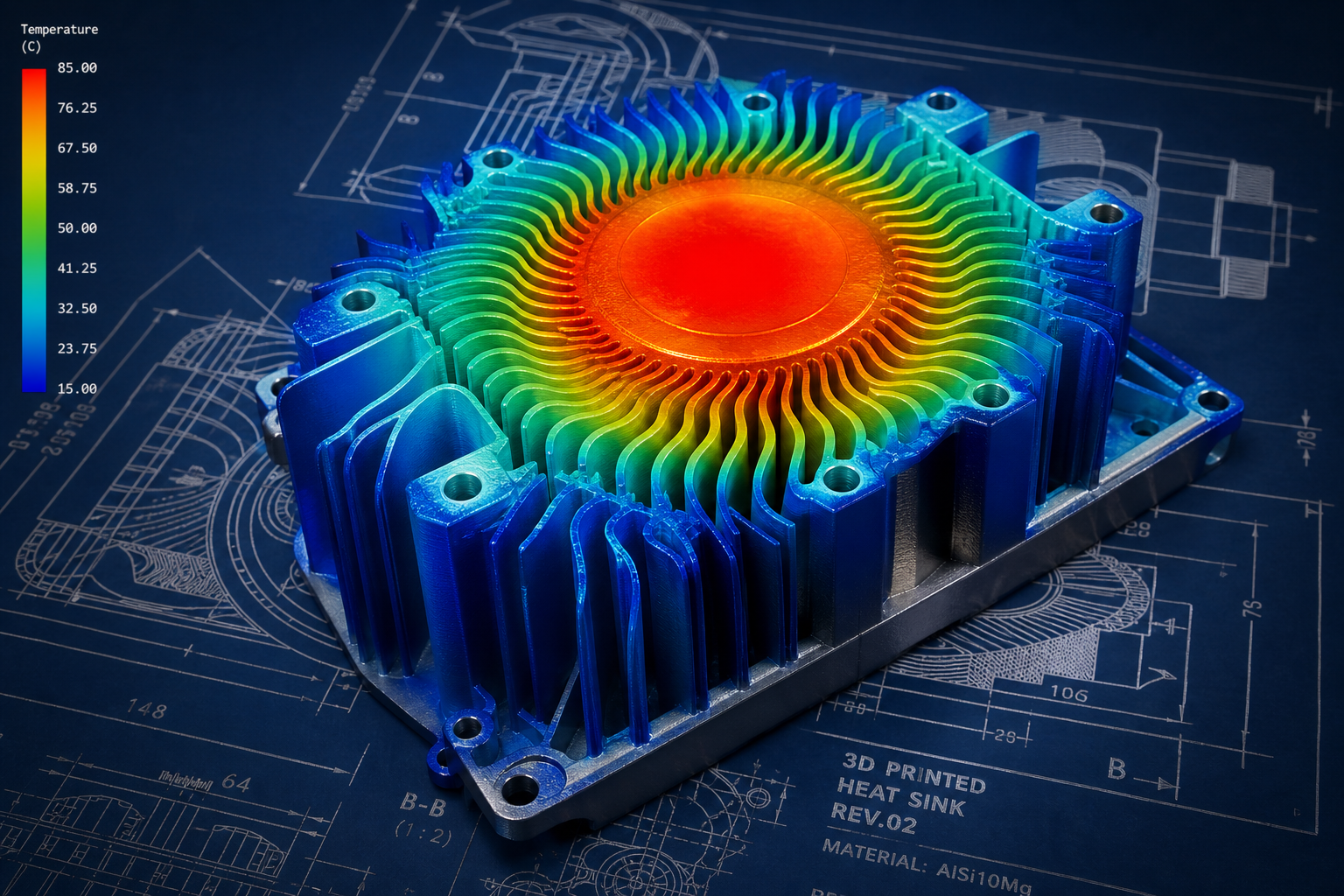
Actively considering heat dissipation paths during the part design stage is an effective way to reduce the risk of thermal deformation. A sound heat dissipation structure design should follow these principles: first, avoid localized mass accumulation; uniform mass distribution helps heat dissipate evenly. Second, add heat-dissipation holes or fins in thick cross-section areas to accelerate heat release. Third, use rib designs to increase the heat-dissipation area without significantly increasing part weight. For metal 3D-printed parts, heat dissipation structure design is especially important. In laser powder bed fusion, areas that are not adequately cooled will undergo more thermal cycles, leading to more pronounced microstructural changes and residual stress accumulation. By designing heat dissipation channels in non-critical areas of the part, heat can be guided away from high-temperature regions more quickly.
Thermal Stress Relief Structural Design
The core idea of thermal stress relief structures is to introduce controllable weak links in the part, allowing thermal stress to be released preferentially at these locations instead of causing overall deformation. Common stress-relief structures include stress-relief slots, flexible connecting arms, corrugated structures, and pre-deformation design. Stress-relief slots are the simplest and most effective design approach. By designing narrow slots in areas expected to experience high stress, space is created for material shrinkage. Flexible connecting arms use the elastic deformation capability of the material, allowing a certain amount of relative displacement while maintaining the connection function, thereby releasing thermal stress.
The Impact of Printing Orientation on Thermal Deformation and Optimization
Printing orientation not only affects surface quality and support requirements, but also directly determines the mode of thermal deformation. In FDM, the shrinkage rate in the Z direction is usually higher than in the X/Y directions because the interlayer bonding strength is lower than the in-layer strength. Therefore, critical dimensions should be placed in the X/Y plane whenever possible. In metal printing, orientation determines the direction of heat flow; heat is mainly conducted downward to the build plate through the printed portion, so the bottom of the part experiences more thermal cycles. Strategies for optimizing printing orientation include arranging critical mating surfaces along the Z direction to obtain better surface quality and avoiding additional deformation of cantilever structures under thermal stress.
Methods for Thermal Deformation Compensation Design
Thermal deformation compensation is an active design strategy that pre-introduces deviations opposite to the expected deformation direction in the CAD model so that, after printing, the part reaches the designed dimensions once thermal deformation has occurred. This method is most widely used in metal 3D printing and usually requires process simulation to determine the compensation amount. The steps for implementing thermal deformation compensation include: first, perform printing process simulation to predict the amount and direction of deformation; then apply reverse scaling or shape offset to the corresponding areas in the CAD model based on the simulation results; finally, verify the compensation effect through test prints and iteratively adjust the compensation parameters. For batch-produced parts, building a database of compensation parameters can significantly improve first-pass yield in subsequent parts.
The Influence of Material Selection on Thermal Performance
Different materials differ significantly in thermophysical properties, which directly affects the degree of thermal deformation. The glass transition temperature, thermal expansion coefficient, thermal conductivity, and crystallization behavior of a material are all important design considerations. For example, ABS has a higher thermal expansion coefficient than PLA, so it is more prone to thermal deformation in FDM printing. Semi-crystalline materials undergo crystallization shrinkage during cooling, with shrinkage rates reaching 3-5%, far higher than those of amorphous materials. When selecting materials, the operating temperature range, required dimensional stability, and post-processing requirements of the part should all be considered comprehensively. For parts with high precision requirements, priority should be given to materials with low shrinkage and high dimensional stability, or some residual stress can be eliminated through annealing.
Submit a model, drawing, image or written notes. Engineers will review material, process, finishing and delivery based on actual use.