
Introduction: Why Strength Can Differ by 20% in Different Directions from the Same Powder Batch
In the metal laser powder bed fusion (LPBF) process, one often overlooked fact is that test bars printed on the same machine, from the same powder batch, and with the same parameter set can show a 10% to 20% difference in tensile strength when sampled along the build direction (Z direction) versus the in-plane direction (XY direction), while the difference in elongation is often even greater. This is not equipment instability; it is the result of the layer-by-layer melting and rapid solidification mechanism itself. Understanding its causes and proactively managing build orientation during the design stage is a key step in advancing metal 3D printing from “printable” to “reliably usable.”
1. Where Anisotropy Comes From: Melt Pool Thermal History Determines Grain Morphology
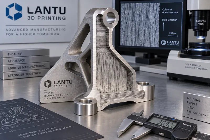
In LPBF, each layer is formed as the laser rapidly scans across a powder bed only tens of microns thick, and the melt pool completes melting and solidification within milliseconds. Heat is conducted mainly downward through the already solidified material, so grains tend to grow epitaxially opposite to the heat flow, namely along the build direction, forming columnar grains that pass through multiple melt pools. Columnar grains have high axial strength, while transverse interfacial bonding is relatively weaker. As a result, the macroscopic behavior is as follows:
1)Z direction (perpendicular to layer interfaces): During tensile loading, the load passes through interlayer fusion lines, and the projected area of defects such as lack of fusion and pores is maximized, so strength and elongation are usually the lowest;
2)XY direction (parallel to layer interfaces): The load is transferred along the grain axis, so strength and ductility are usually higher;
3)45-degree oblique direction: Performance lies between the two, with the highest sensitivity to shear and multiaxial loads, and it is also the orientation where fatigue cracks are most likely to initiate.
Measured results for common materials such as Ti-6Al-4V, 316L, and AlSi10Mg generally follow this pattern. The magnitude of the difference is strongly correlated with energy density, layer thickness, and scanning strategy (chessboard/stripe). Reducing volumetric energy density aggravates lack of fusion and amplifies anisotropy; increasing the interlayer scan rotation angle, such as 67 degrees, can weaken texture and reduce directional differences.
2. Not Every Part Needs Equal Strength in All Directions
A common form of overdesign is to require isotropy regardless of load direction. In practice, the first step in orientation optimization is to identify the part’s principal stress direction, and then decide whether it is worth paying the cost to homogenize performance.
Case A: Rolling bearing housing. A bearing housing used in automation equipment is subjected to radial loads, and its principal stress direction is concentrated in the horizontal plane. In the original plan, the part was placed directly according to its assembly posture, making the Z direction coincide with the load direction, and measured fatigue life fell short of the design value. After rotating the part 90 degrees around the horizontal axis so that the columnar grain axis was roughly parallel to the principal load, fatigue cycles increased by about 40% under the same material and parameters, while printing time increased by only 6% due to a slight increase in support volume.
Case B: Liquid-cooling heat-dissipation flow-channel plate. For this part, the focus is thermal conduction through the channel wall and flatness of the sealing surface, rather than tensile strength. Here, orientation decisions follow two different rules: keep the flow-channel axis as perpendicular to the build direction as possible to suppress overhang collapse, and avoid placing the sealing surface on the Z-direction top layer to achieve better flatness. This shows that the “optimal orientation” is always the result of a specific function, and there is no universal answer.
3. Four Engineering Rules for Orientation Decisions
Rule 1: Prioritize principal stress. Keep the main tensile stress direction as parallel as possible to the columnar grain axis, meaning at 0 degrees or 180 degrees to the build direction, and avoid having the principal stress pass directly through interlayer interfaces.
Rule 2: Avoid critical features. Place key features such as threaded holes, sealing surfaces, mating surfaces, and thin-wall roots on XY-direction surfaces, or at least away from the topmost and bottommost Z-direction layers, to reduce stair-stepping effects and powder adhesion.
Rule 3: Link supports with thermal stress. A change in orientation also changes the overhang area and interlayer cooling rate. Overhang angles above 45 degrees require additional supports, and support contact points can become stress concentration sources. For long, thin parts, the long axis should be aligned with the build direction, using gravity and the in-plane stress direction to suppress warpage rather than the opposite.
Rule 4: Reserve allowance for post-processing. Functional surfaces that must be machined should be given a 0.3 to 0.5 mm allowance during orientation planning, allowing cutting to remove the printed surface layer and thereby bypass the impact of surface roughness and near-surface defects on fatigue life.
4. How Heat Treatment and Post-Processing Reduce Directional Differences
Orientation optimization cannot solve every problem because the columnar grain texture still exists. In engineering practice, the following methods are usually combined:
1)Stress-relief annealing: Holding below the phase transformation temperature releases residual stress and stabilizes dimensions. It provides limited improvement in strength anisotropy but significantly reduces the risk of cracking and distortion;
2)Hot isostatic pressing (HIP): Internal pores are closed under high temperature and high pressure, compensating for the Z-direction defect sensitivity weakness. This is a common step for load-bearing aerospace and medical parts;
3)Solution treatment plus aging: For heat-treatable strengthening alloys such as Ti-6Al-4V and AlSi10Mg, this changes the phase composition and can significantly reduce directional differences, but the curve must be customized according to the material system;
4)Machining and surface treatment: Removing unmelted particles and rough peaks and valleys on the surface often contributes more to fatigue performance improvement than orientation adjustment itself.
It should be emphasized that the anisotropy coefficient of the same material is not identical under different heat treatment conditions. Therefore, the “anisotropy coefficient” must be written into acceptance documents together with the heat treatment condition, rather than specifying only the material grade.
5. Embedding Orientation Review into the Process: An Actionable Checklist
To avoid discovering orientation problems only during prototyping, it is recommended to incorporate the following checks into the DFM review:
1) Has the principal stress direction and safety factor requirement been specified?
2) Have critical mating surfaces been kept away from the Z-direction top layer?
3) Does the overhang angle exceed 45 degrees? Are the corresponding supports feasible and easy to remove?
4) Is there any weak cross-section with an excessive aspect ratio in the Z direction?
5) Has machining allowance been reserved and have datums been specified?
6) Have the heat treatment condition, whether HIP is applied, and the anisotropy coefficient been written into the drawings and acceptance standards?
7) Are orientation diagrams and screenshots of the support plan attached for confirmation by both the quoting and manufacturing parties?
By adding these seven items to the review form, orientation changes from “the printing engineer’s experience” into “a verifiable engineering input.” For buyers, this means more predictable quotations and lead times; for manufacturers, it means significantly fewer rework events and prototyping iterations.
Conclusion
Anisotropy in metal 3D printing is not a defect, but a physical attribute of the process. It can be utilized through orientation design, allowing columnar grains to carry loads along the principal load direction; it must also be controlled through heat treatment, HIP, and machining to compress directional differences into an acceptable range. For engineering teams, the practical approach has three steps: first identify the principal stress direction, then select the build orientation accordingly, and finally use post-processing and acceptance standards to lock in the orientation benefits. By writing these three steps into the DFM review, metal additive manufacturing can move from “printing the shape” to “delivering reliable performance.”
Submit a model, drawing, image or written notes. Engineers will review material, process, finishing and delivery based on actual use.