
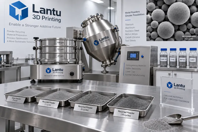
Introduction: Recycled powder is not "saved new powder," but a raw material whose condition can drift
In metal powder bed fusion (LPBF/SLM) production, the unfused powder from each build is recovered, sieved, blended, and put back into use. Taking a medium-capacity machine as an example, the powder utilization rate in a single build is usually between 30% and 60%, which means that nearly half of the powder enters the reuse loop. If recycled powder is treated as an equivalent substitute for new powder, the condition differences between the first, fifth, and tenth reuse cycles may suddenly appear as defects: streaks during powder spreading, interlayer lack of fusion, increased porosity, excessive oxygen content, and batch-to-batch fluctuations in mechanical properties. The real engineering question is not "whether it can be recovered," but "up to which batch it can be reused, at what blending ratio, and under what release criteria."
1. Aging mechanisms of recycled powder: three changes occur at the same time
The degradation of powder during reuse is not one-dimensional; it is the superposition of geometric morphology, chemical composition, and surface physical state.
1) Particle size distribution drift (PSD coarsening). The heat-affected zone around the melt pool produces spatter and satellite particles. Fine powder is preferentially carried away or agglomerated during gas-flow classification and sieving, causing D10 and D50 to gradually shift upward. A typical phenomenon is that new powder may have a D50 of about 35 μm, which can rise to 42-45 μm after 8-10 reuse batches, while the fine powder fraction (<15 μm) may decrease by more than 30%. Coarser particle size directly raises the minimum powder-spreading thickness in the layer-thickness direction, reducing build stability for thin walls and fine flow channels.
2) Oxygen/nitrogen increase and surface oxidation. Powder has a large specific surface area, and every exposure during powder removal, sieving, and transfer can adsorb moisture and oxygen. For TC4 titanium alloy, common industry practice is to control oxygen content within the range of 0.13%-0.20%. Once the oxygen increase in recycled powder exceeds 0.02% relative to the new-powder baseline, elongation shows a measurable decline. For AlSi10Mg aluminum alloy, the effect appears as thickening of the oxide film in the melt and a stronger tendency toward balling. 316L stainless steel has relatively wider tolerance, but nitrogen increase can still change austenite stability.
3) Morphology degradation and flowability decay. As the proportion of satellite particles, irregular fragments, and partially sintered agglomerates increases, sphericity decreases. The most direct consequences of sphericity degradation are worse Hall flow rate and lower apparent density: new powder may have a Hall flow rate of 15-18 s/50 g, while late-cycle recycled powder may extend to more than 22 s/50 g, manifesting as drag streaks during recoater spreading, local powder shortages, and uneven layer thickness.
2. Blending ratio control: converting "reuse cycles" into "releasable proportions"
Recycled powder cannot be used indefinitely, but it should not be scrapped by a fixed cycle count in a one-size-fits-all way. A more robust engineering approach is to establish a three-part rule: aging indicators, blending ratio, and release criteria.
Stage 1: Use dilution by blending instead of direct reuse. A common strategy is to blend recycled powder with new powder at a fixed ratio, such as 70:30 or 50:50. After blending, the powder is mixed in a powder mixer at low speed for a short time to avoid secondary damage to sphericity, and then sampled for testing. The essence of blending is to use new powder to pull the particle size distribution and oxygen content back into the process window.
Stage 2: Set graded blending ranges. It is recommended to classify batches in the records according to test results: when PSD drift is <5% and oxygen increase is <0.01%, 70:30 blending is allowed; when PSD drift is 5%-10% and oxygen increase is 0.01%-0.02%, the ratio is tightened to 50:50; when any indicator exceeds the limit, that batch should no longer enter the build chamber and should be downgraded for non-critical prototype trials or returned to the supplier for handling. The grading ranges must be calibrated using the plant's own measured data and must not be copied directly from another facility.
Stage 3: Set hard upper limits and mandatory scrapping. Even if every test passes, an upper limit for cumulative reuse cycles should be set, typically 8-12 cycles for most metal systems, or an upper limit for cumulative thermal exposure time should be defined. Once the limit is reached, the powder must be scrapped. The reason is that some degradation, such as internal microcracks in particles or lattice strain, cannot be detected at low cost through conventional testing methods.
3. Testing methods and sampling representativeness
Whether blending ratio control can be implemented depends on whether the testing is reliable. The following frequencies and test items are recommended:
Particle size distribution: Laser diffraction method, sampled once after each batch is blended. The sampling point should be at the discharge outlet of the powder mixer rather than the surface of the container, to avoid false data caused by segregation. Focus on D10/D50/D90, not only D50.
Flowability: Use a Hall flowmeter, or funnel method, together with apparent density, such as Hall flow rate and Carr index, for combined assessment. Looking only at flow rate can easily miss agglomeration-type degradation.
Chemical composition: Oxygen, nitrogen, and hydrogen analysis by inert gas fusion should be mandatory for every batch. This is especially critical for titanium alloys and aluminum alloys. It is recommended to use the increase relative to the new-powder baseline as the criterion rather than the absolute value.
Morphology: Scanning electron microscopy (SEM) spot checks should be performed every 5 batches or whenever an abnormal defect appears. The focus should be on quantifying the proportion of satellite particles and broken particles.
Process validation: For each blended batch, retain a set of standard specimens, such as tensile bars or densification coupons, and use relative density and tensile data to verify whether the release rules need to be tightened.
4. Implementation points and common misconceptions
Misconception 1: Looking only at reuse cycles. The same number of reuse cycles can correspond to very different thermal exposure in continuous full-plate production of small parts versus sparse production of large parts. Cycle count is not a reliable proxy variable.
Misconception 2: The finer the sieve mesh, the better. Excessive sieving removes a large amount of usable fine powder, increasing cost and changing the particle size distribution. The sieve mesh should match the nominal particle size range of the powder. In general, a specification slightly larger than D90 is selected, and the screen should be regularly checked for damage.
Misconception 3: Ignoring environmental steps. If powder removal, sieving, and transfer are performed in an environment without humidity control, pore defects caused by moisture absorption are often misjudged as process-parameter problems. It is recommended to keep the sieving room humidity below 40% RH and to pre-dry powder that has been exposed for a long time.
Implementation checklist: Establish a batch history for the powder in each build, including reuse cycles, blending ratio, test values, and equipment used; ensure bidirectional traceability between blending records and part serial numbers; when any abnormal defect is triggered, first trace back the PSD and oxygen/nitrogen data of that batch before adjusting process parameters.
Conclusion
The reuse of metal 3D printing powder is essentially a chain-management issue linking raw material condition, process window, and finished-part performance. Only by quantifying particle size drift, flowability decay, and oxygen/nitrogen increase as measurable indicators, and then constraining them within the process window through graded blending ratios and hard upper limits, can recycled powder be transformed from a cost risk into a controllable cost advantage. For the delivery party, the value of this rule set lies not in "how much powder was saved," but in ensuring that the 200th build of parts has a performance baseline comparable to that of the 1st build.
Submit a model, drawing, image or written notes. Engineers will review material, process, finishing and delivery based on actual use.