
Introduction: The Overlooked Quality Gate of Cleanliness
In the delivery of metal 3D-printed parts, especially SLM/LPBF components, attention is often focused on “printing parameters” such as laser power, scanning speed, and layer thickness. Yet one fact is frequently overlooked: the moment a part is removed from the build chamber, it is still only a semi-finished product. Supports remain attached to the surface, unmelted metal powder is trapped inside cavities and channels, and sintered particles adhere to the surface. What truly determines whether the part can be installed and used is often not the printing itself, but the subsequent support removal and cleaning process. In the industry, this stage is known as cleanliness control. It does not create a visually striking effect, but it is directly related to assembly jamming, vacuum leakage, fatigue life, and release compliance for medical and aerospace components.
1. Why Support Removal and Cleaning Are the Hidden Quality Gate in Metal 3D Printing
Metal powder bed fusion relies on support structures to conduct heat away and resist warping deformation, so contact points between the supports and the part are inevitable. After printing, these supports must be completely separated without damaging the part surface. At the same time, unmelted powder around the laser melt pool adheres to the part surface. This is especially problematic in internal geometries such as conformal cooling channels, lattice structures, and thin-walled cavities. Once powder remains inside, it can block channels, contaminate media, or even act as abrasive particles in assembled friction interfaces.
Take conformal cooling molds as an example. Their internal cooling channels often have diameters of only 3–8 mm. If residual metal powder is not removed, cooling efficiency during injection molding will be significantly reduced, and particles may be carried into the molded products. In medical device components, residual particles on surfaces and inside cavities must meet strict cleanliness grades, such as ISO 16232 particle counting requirements; otherwise, the parts cannot pass biocompatibility and release audits. Therefore, support removal and cleaning are not optional cosmetic treatments, but engineering processes that affect function, reliability, and compliance.
2. Support Removal: Choosing Methods from Mechanical Removal to Precision Separation
Support removal methods should be selected in levels according to support type, part material, and precision requirements.
(1) Manual removal and cutting pliers. This method is suitable for small and medium-sized parts with relatively soft supports and fewer contact points. The key lies in the design of the contact points: the support-to-part contact section is usually made thinner than the support body itself, known as a “neck-down” design. The contact diameter is controlled at 0.2–0.5 mm so that stress concentrates at the contact point rather than in the part body during separation, leaving only tiny protrusions after removal.
(2) Machining and milling removal. For high-hardness materials such as Inconel 718 and titanium alloys, or for large-area block supports, CNC milling is more efficient for removing support roots and can better control the flatness of the residual surface.
(3) Wire cutting and electrical discharge machining (EDM). When supports are located in areas that cannot be mechanically accessed and the part cannot withstand cutting forces, slow wire EDM or EDM can achieve “non-contact separation.” However, EDM forms a recast layer, so stress relief and surface treatment should be added after removal.
(4) Laser and benchwork finishing. For mating surfaces with high requirements, fine files, oilstones, or laser micro-finishing are used at the end to dress the roots of contact points and make residual protrusions flush with the datum surface, ensuring the required Ra and flatness of assembly surfaces.
Regardless of the method used, key mating surfaces should be rechecked for dimensions and roughness after support removal. The roughness of support contact surfaces is usually 2–4 times higher than that of as-built surfaces. If these areas fall within sealing or sliding-fit zones, they must be included in the subsequent finishing plan.
3. Powder Removal: Residual Control in Internal Channels and Complex Cavities
Powder removal is the core challenge of cleanliness control and must be carried out as soon as possible after opening the build chamber and before the powder absorbs moisture. Common methods include:
(1) Vacuuming and vibration powder removal. The part is placed at a negative-pressure vacuum station and combined with pneumatic or ultrasonic vibration so that loose powder inside cavities naturally flows out through openings. For closed cavities, powder removal holes must be reserved in advance, with a recommended diameter of at least 2 mm; otherwise, internal powder cannot be removed.
(2) Compressed air and inert gas purging. Dry compressed air or nitrogen/argon is used to purge internal channels at 0.3–0.5 MPa, and the airflow direction should follow the channel direction. For flammable reactive powders such as titanium alloys and aluminum-magnesium alloys, operations must be performed in explosion-proof and inert environments to avoid the risk of dust cloud ignition.
(3) Dedicated channel flushing. For through-channels such as conformal cooling channels, high-pressure water or dedicated channel cleaning equipment can be used for repeated flushing until no visible particles are discharged, followed by flow-pressure drop testing to confirm channel patency.
It should be emphasized that inadequate powder removal is the root cause of many “post-process defects.” Residual powder may sinter during subsequent heat treatment, forming hard agglomerates that are difficult to remove. If it remains in gears or sliding pairs, it becomes abrasive media and accelerates wear.
4. Cleaning Process: From Ultrasonic Cleaning to Multi-Stage Solvent Cleaning
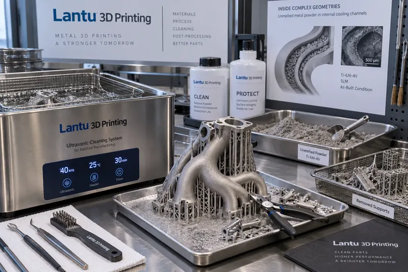
After support removal and powder removal, adhered sintered particles, oil, fingerprints, and chips may still remain on the part surface, requiring a systematic cleaning process. A multi-stage cleaning workflow is commonly used in engineering practice:
Ultrasonic cleaning: frequency 25–40 kHz, temperature 40–60°C, and time 5–15 minutes. Lower frequencies are more suitable for removing larger particles, while higher frequencies are better for fine gaps. The cleaning solution is typically deionized water with a neutral detergent. For reactive metals, chlorine-containing solvents should be avoided to prevent chloride-ion-induced pitting and stress corrosion.
Rinsing and passivation: after cleaning, multi-stage rinsing with deionized water is used.
Submit a model, drawing, image or written notes. Engineers will review material, process, finishing and delivery based on actual use.