
Introduction: Why a Single Process Is Increasingly Insufficient
Pure additive manufacturing processes such as LPBF/SLM and SLS can form complex internal cavities and conformal structures, but freeform surface roughness is typically around Ra 6-12 μm. Dimensional accuracy is affected by thermal deformation and powder sintering, making it difficult to directly meet assembly and sealing requirements. Pure subtractive manufacturing, such as five-axis CNC machining, delivers high surface quality and stable dimensions, but material utilization is low; in titanium alloy machining, more than 90% of the material may become chips. In addition, deep cavities and internal flow channels may be completely unreachable by cutting tools. Combining the two in one process chain—using additive manufacturing for near-net shaping and subtractive manufacturing for final finishing—is the starting point of hybrid additive-subtractive manufacturing.
1. What Is Hybrid Additive-Subtractive Manufacturing?
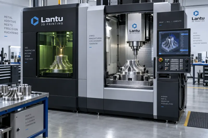
There are two mainstream forms. The first is an integrated machine, where a laser cladding or powder-fed deposition head and a five-axis milling spindle are integrated on the same worktable, allowing additive and cutting operations to alternate within the same coordinate system. The second is process separation, where 3D printing is first used to produce a near-net-shape blank, which is then transferred to CNC machining for high-precision features. The former offers the best datum consistency, while the latter has lower equipment modification costs and is easier to implement in existing production lines. For most small- and medium-batch metal parts, the separated-process approach is the more cost-effective entry point.
2. Three Key Control Points in Process Integration
First, datum alignment. The additive stage must reserve positioning datums that match the CNC fixture, usually a 3-2-1 datum plane setup or a one-face-two-pin structure. The clamping surface of the printed blank should include a 0.3-0.5 mm machining allowance for finish milling and leveling. Second, stock allowance allocation. Only features that cannot be reached by tools or would require excessive material removal should be preformed by additive manufacturing. Other planes, hole patterns, and sealing surfaces should be left for CNC finishing. A typical allowance is 0.2-0.4 mm per side for semi-finishing plus 0.05-0.1 mm for finishing. Third, clamping consistency. After the printed part is removed from the powder bed, deformation must first be released through stress-relief annealing, such as holding at 300-400°C for 2-4 hours. Otherwise, clamping stress may rebound during cutting and cause dimensional drift.
3. Precision Control: From Thermal Deformation to In-Process Inspection
Additive blanks contain residual stress and can rebound after cutting removes constraints. Countermeasures include aging and stress relief before finishing, leaving uniform stock during roughing, and performing final finishing after semi-finishing. For high-precision parts, on-machine verification (OMV) or first-article confirmation using a coordinate measuring machine (CMM) should be applied, with measured deviations fed back to compensate the toolpath. In the tolerance chain, additive blanks are generally controlled to IT12-IT14, while the final subtractive stage brings accuracy to IT7-IT8. Critical sealing surfaces can achieve Ra 0.8 μm or better.
4. Typical Applications and Parameters
Conformal cooling mold inserts: additive manufacturing forms the conformal water channels, while CNC finishes the parting surfaces and ejector pin holes. The water channel surface roughness should be controlled at Ra 3-5 μm to reduce scaling. Aerospace integral impellers: additive manufacturing preforms near-net-shape blades, and five-axis milling finishes the blade profiles and hub, with a 0.3 mm allowance per side. Medical titanium alloy implants: additive manufacturing forms porous structures in one piece, while CNC finishes mating surfaces and threads. The common logic across these three part types is to use additive manufacturing for material utilization and subtractive manufacturing for dimensional and surface quality.
5. Common Defects and Prevention
Tool marks and chatter are often caused by uneven allowance or excessive tool length-to-diameter ratio. Countermeasures include equalizing layer-by-layer allowance, using short and rigid tools, and limiting cutting speed. Insufficient allowance can lead to uncut printed skin, so allowance visualization checks should be performed on the print model. Datum drift comes from inadequate annealing, so stress relief must be included as a mandatory step in the process sheet. Clamping deformation can be reduced by using soft jaws, vacuum chucks, and support bridges to distribute clamping force.
Conclusion
Hybrid additive-subtractive manufacturing is not simply placing two machines together. It is about connecting datum alignment, allowance allocation, stress relief, and in-process inspection into a controllable process chain. When implementing it, companies should start with the separated-process approach, build standard operations around datum alignment and allowance allocation, and then use on-machine measurement as a closed loop to maintain dimensional accuracy. Only then can the complexity advantages of additive manufacturing be converted into the consistent quality of subtractive manufacturing.
Submit a model, drawing, image or written notes. Engineers will review material, process, finishing and delivery based on actual use.