
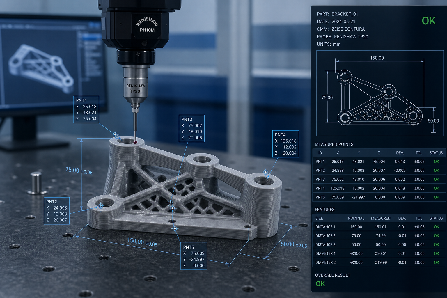
Why Inspectability Design Is Crucial
In precision engineering, there is a saying: you cannot control what you cannot measure. For 3D printed parts, because of the inherent variability of the process, quality inspection and dimensional verification are even more critical than in traditional manufacturing. Inspectability design is a methodology that fully considers later inspection requirements during the design stage, ensuring that once a part is printed, it can be inspected efficiently, accurately, and economically for dimensions and performance. The complex geometries of 3D printed parts pose major challenges to traditional inspection methods. CMM probes may not be able to reach enclosed areas; optical scanners may produce missing data in deep grooves or shadowed regions; and although X-ray CT can detect internal defects, it is extremely expensive. If inspectability is not considered during the design stage, the part may be impossible to verify, creating quality risks.
Design Principles for Inspection Datums
Inspection datums are the reference framework for all subsequent dimensional measurements, and their design quality directly determines the reliability and repeatability of measurement results. According to GD&T standards, inspection datums should follow the principles of maximum priority, functional priority, and stability priority. In 3D printed parts, because the build platform plane usually has high flatness, the surface in contact with the platform can be used as the primary datum. When designing inspection datums, it is important to ensure that the datum features have sufficient size and stability. The flatness of the datum surface should be controlled within 0.05 mm, and the diameter tolerance of the datum hole should not exceed H7. For complex curved-surface parts that cannot provide three orthogonal datum planes, special inspection datum features can be designed, such as inspection process holes, inspection planes, or inspection bosses. These features can be placed in non-critical areas and removed by post-processing if needed after inspection.
Measurement Accessibility Design
Measurement accessibility refers to the ability of the sensor or probe of the measuring equipment to reach the feature being measured. In the design of 3D printed parts, measurement dead zones should be proactively avoided. Common measurement dead zones include the bottoms of deep holes with a depth-to-diameter ratio greater than 5:1, the interiors of enclosed cavities, narrow passages smaller than 3 mm, and bottom surfaces surrounded by high side walls. Design strategies for improving measurement accessibility include creating inspection windows in enclosed cavities, with window dimensions that allow a probe or optical scanner field of view to enter; designing through-holes rather than blind holes for deep-hole features; reserving sacrificial inspection holes for cavities that must remain closed, then sealing them with plugs after inspection; and designing measurement aid planes for complex curved surfaces to convert surface dimensions into measurable planar features.
Application of GD&T in 3D Printed Parts
GD&T is an international standard for precisely expressing design intent and is especially important for 3D printed parts. Traditional tolerance notation cannot fully express the assembly and functional requirements of complex geometries, whereas GD&T provides a more precise technical communication language by defining datums, tolerance zone shapes, and positions. In 3D printed parts, the following GD&T symbols should be emphasized: flatness and straightness to control the surface quality affected by the build platform; circularity and cylindricity to control the accuracy of rotational features; position to control the relative locations of hole patterns and mounting features; and profile to control the form accuracy of freeform surfaces. When applying GD&T, the datum system must be clearly defined; otherwise, the tolerance annotations will lose their reference framework.
Design and Selection of Inspection Plans
Different 3D printed parts require different inspection plans. For parts with simple geometries, contact CMM measurement is sufficient; for parts with freeform surfaces, optical scanning or laser tracking is more suitable; for internal defect inspection, industrial CT is the best choice; and for mass-produced parts, dedicated gauges can be considered to improve inspection efficiency. Determining the inspection plan during the design stage can guide design optimization in reverse. For example, if optical scanning is chosen as the primary inspection method, high-depth-to-width grooves should be avoided; if CMM is chosen, sufficient probe approach space must be ensured near the features being measured. For critical parts that require 100% inspection, the feasibility of automated inspection should be considered during design.
End-to-End Digitization from Design to Inspection
Modern quality management systems support end-to-end digitization from design to inspection. By directly annotating GD&T and inspection requirements in the CAD model, inspection programs can be generated automatically, enabling an efficient design-as-inspection workflow. Digital inspection records can also be linked with 3D printing process parameters to build a quality traceability data chain. The key steps to implementing end-to-end digitization include adding ...
Submit a model, drawing, image or written notes. Engineers will review material, process, finishing and delivery based on actual use.