
lantu3D

Design for Assembly of 3D Printed Parts: Optimizing from DFA Principles to Real Assembly Processes

Design for Assembly (DFA) for 3D printed parts: optimizing from DFA principles to real assembly workflows. Introduction: The importance of design for assembly. In traditional manufacturing, DFA mainly focuses on reducing part count and simplifying assembly steps. In the field of 3D printing, DFA has been radically expanded—through integrated printing, snap-fit features, living hinges, and similar techniques, complex products that once required dozens of parts can be reduced to just one or two printed components, achieving the ultimate goal of "design equals assembly." According to a Boeing case study, 3D-printed parts optimized with DFA reduced part count by 90%, shortened assembly time by 95%, and improved reliability by 30%.
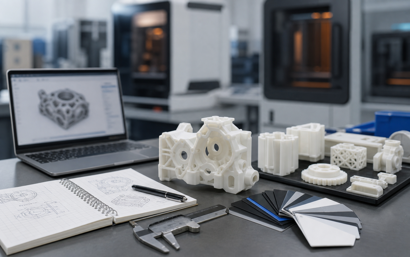
Design for Assembly of 3D Printed Parts: Optimizing from DFA Principles to Real Assembly Processes
## Design for Assembly of 3D Printed Parts: Optimizing from DFA Principles to Real Assembly Processes ## Introduction: The Importance of Design for Assembly Design for Assembly (DFA) is a critical part of product development and directly affects manufacturing cost, assembly efficiency, and product quality. In traditional manufacturing, DFA mainly focuses on reducing part count and simplifying assembly steps. In the field of 3D printing, however, the meaning of DFA has been radically expanded—through integrated printing, snap-fit designs, living hinges, and related technologies, complex products that once required the assembly of dozens of parts can be simplified into just one or two printed components, achieving the ultimate goal of "design equals assembly." According to a Boeing case study, 3D-printed parts optimized with DFA reduced part count by 90%, shortened assembly time by 95%, and improved reliability by 30%. However, DFA for 3D printing is not simply about "merging parts." It is a complex systems engineering effort that must account for printing process constraints, material properties, tolerance accumulation, post-processing requirements, and long-term reliability. Poorly designed "integrated" parts may be impossible to print, impossible to assemble after printing, or prone to failure in service. Therefore, establishing a DFA methodology suitable for 3D printing is essential. ## Reinterpreting the Basic DFA Principles for 3D Printing The ten traditional DFA principles need to be reinterpreted for the era of 3D printing: **Principle 1: Reduce Part Count** 3D printing allows multiple parts to be merged into one, but the following must be considered: - Whether the merged part is printable (no sealed cavities, powder removal possible) - Whether merging affects function (motion interference, thermal expansion differences) - Whether merging reduces maintainability (wear parts cannot be replaced) **Principle 2: Standardization and Modularity** The advantage of 3D printing is customization, but standardized interfaces should still be retained: - Use standard threads and standard snap-fit dimensions - Design modular interfaces to allow partial replacement - Maintain interchangeability of critical dimensions **Principle 3: Self-Location Design** 3D printed parts should include self-locating features: - Asymmetric locating pins (to prevent incorrect orientation) - Tapered lead-ins (to simplify alignment) - Color coding or tactile markers (to distinguish similar parts) **Principle 4: Reduce Assembly Directions** Traditional DFA requires all assembly to be completed from a single direction; in 3D printing: - Use living hinges to achieve "zero assembly" (printed and assembled at once) - Design flexible snap-fits that allow elastic deformation along one direction - Use magnetic connections to enable rapid alignment from multiple directions **Principle 5: Easy Gripping and Handling** After printing, parts often require post-processing: - Design dedicated gripping surfaces (flat and texture-free) - Reserve lifting eyes or handles for large parts - Consider gloved operation (medical and food industries) ## Tolerance Design and Fit Selection Because 3D printing has limited accuracy, tolerance design is especially critical. Improper tolerances can result in fits that are too tight (parts cannot be inserted) or too loose (rattle and noise). **Dimensional Capability by Process** - FDM: ±0.3–0.5 mm (standard), ±0.1–0.2 mm (high precision) - SLA: ±0.1–0.2 mm (standard), ±0.05 mm (high precision) - SLS: ±0.3–0.5 mm (affected by powder shrinkage) - Metal printing: ±0.1–0.3 mm (affected by heat-affected zones) **Fit Selection Guide** 1. Clearance fit (H7/g6): for sliding or rotating parts, clearance 0.05–0.2 mm 2. Transition fit (H7/k6): for precise positioning, essentially no clearance 3. Interference fit (H7/p6): for fastening connections, interference 0.02–0.1 mm **Controlling Tolerance Stack-Up** In multi-part assemblies, tolerances accumulate. Control methods include: - Unifying datum surfaces (Datum A/B/C system) - Converting chain dimensions into coordinate dimensions - Setting tolerance bands of ±0.1 mm for critical dimensions - Relaxing non-critical dimensions to ±0.5 mm **Compensation Strategies** Actual 3D printed dimensions are often smaller than nominal values (resin shrinkage, sintering shrinkage), so you should: - Increase hole dimensions by 0.1–0.3 mm - Reduce shaft dimensions by 0.05–0.15 mm - Use test prints to verify actual deviation ## Assembly Sequence Planning and Interference Checking Even integrated printed parts may still require assembly of moving components or electronic parts. Proper assembly sequence planning can avoid the frustrating situation of "discovering halfway through that the parts no longer fit." **Principles for Optimizing Assembly Sequence** 1. Inside first, outside second: install internal parts before the housing 2. Bottom first, top second: use gravity to aid positioning 3. Large first, small second: large parts provide the reference, small parts fill in 4. Difficult first, easy second: complete difficult steps early when the operator is freshest 5. Final adjustment last: leave one adjustable step to compensate for accumulated errors **Digital Verification of Interference Checks** Use CAD software interference-check functions: - Static interference: overlapping regions between parts - Dynamic interference: collisions during movement - Clearance checks: areas with minimum clearance < 0.5 mm - Tool access space: room for screwdrivers and wrenches **Interference Issues Specific to 3D Printing** - Support remnants: bumps left after support removal may cause interference - Layer lines: layer texture can make actual dimensions larger - Thermal deformation: cooling after printing may cause distortion and interference - Post-processing allowance: sanding and bead blasting remove material and may increase clearance ## Design Considerations for Moving Parts One of the biggest advantages of 3D printing is the ability to print moving parts directly (gears, hinges, sliders, and so on), but poor design can lead to jamming or rapid wear. **Gear Design Parameters** - Module: ≥0.5 (FDM), ≥0.3 (SLA) - Pressure angle: 20° (standard), 14.5° (optimized for 3D printing) - Backlash: 0.1–0.3 mm to compensate for printing errors - Root fillet radius: R ≥ 0.3 mm to avoid stress concentration - Face width: ≥3 mm (FDM), ≥1.5 mm (SLA) **Sliding Fit Design** - Fit clearance: 0.1–0.2 mm (FDM), 0.05–0.1 mm (SLA) - Surface treatment: design longitudinal texture (oil-retaining grooves) to reduce friction - Material selection: use different materials (for example, PLA shaft + PETG sleeve) to reduce wear - Lubrication design: reserve oil ports or oil-retaining grooves **Bearing and Bushing Design** - Bearing bore: enlarge by 0.1 mm to compensate for shrinkage - Bushing length: at least 1.5 times the shaft diameter to ensure stability - Axial location: design retaining-ring grooves or shoulders - Heat treatment: metal-printed bearing components require heat treatment to increase hardness ## Quick Assembly Tools and Fixture Design To improve assembly efficiency, dedicated fixtures and tools can be designed—and these fixtures themselves can also be made by 3D printing. **Positioning Fixture Design** - Pin location: use two cylindrical pins (3–5 mm diameter) with positioning accuracy of ±0.05 mm - Face location: use three support points (following the 3-2-1 principle) - Groove location: use T-slots or dovetail grooves to prevent rotation **Clamping Fixture Design** - Quick clamps: design clamp interfaces suitable for 3D printed parts - Magnetic fixtures: embed magnets (NdFeB N52) for rapid clamping - Vacuum adsorption: design sealing edges to use vacuum suction for thin-wall parts **Assembly Guidance Tools** - Guide pins: help align holes, with a diameter 0.5 mm smaller than the bolt - Tapered guidance: 1 × 45° lead-in chamfers to guide assembly - Elastic fixtures: temporary holding clips made from flexible material (TPU) ## Assembly Quality Inspection Standards After assembly, inspection standards must be established to ensure quality. **Dimensional Inspection** - Critical dimensions: measure with calipers or micrometers, tolerance ±0.2 mm - Geometric tolerances: use dial indicators to check runout and coaxiality - Clearance inspection: use feeler gauges to check fit clearance; 0.05–0.2 mm is acceptable **Functional Testing** - Motion test: manual operation 10 times, with no sticking or abnormal noise - Load test: apply 1.5 times the working load for 5 minutes - Life test: simulate 1,000 assembly/disassembly cycles **Appearance Inspection** - Assembly gap: uniform and consistent, deviation < 0.3 mm - Symmetry: deviation between left and right symmetrical parts < 0.5 mm - Surface quality: no scratches, dents, or support residue ## Conclusion Design for assembly of 3D printed parts is an emerging discipline that integrates traditional DFA principles with the characteristics of additive manufacturing. From reducing part count to optimizing tolerance design, from planning assembly sequences to designing moving parts, from creating dedicated fixtures to establishing inspection standards, every step
Next Step Is this close to what you need?

Submit a model, drawing, image or written notes. Engineers will review material, process, finishing and delivery based on actual use.

Submit Request Ask First