
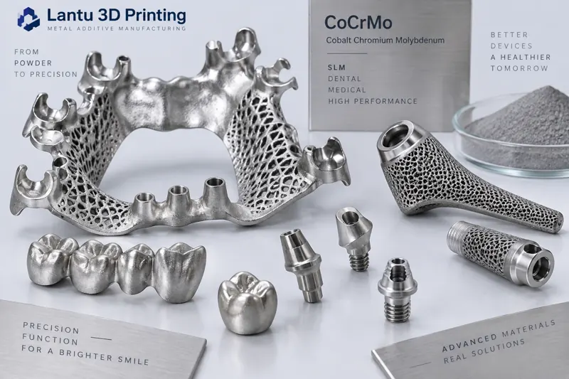
Introduction: Why CoCr Is a Preferred Metal for Dental and Medical Implants
In removable partial denture frameworks, implant-supported dental restorations, and trauma and spinal orthopedic implants, cobalt-chromium alloy (CoCrMo) has long competed with titanium alloys. Compared with commercially pure titanium, CoCrMo offers higher yield strength (commonly about 450-650 MPa Rp0.2 in the annealed condition), better wear resistance, and an elastic modulus closer to the bone-implant transition zone. Compared with 316L stainless steel, it provides significantly better corrosion resistance and biocompatibility. For 3D printing, the challenge is not simply “whether it can be melted,” but whether it can be melted densely, consistently, and in compliance with regulations. Dental framework wall thicknesses are often only 0.3-0.5 mm, and any lack-of-fusion defect can directly compromise wearing safety. Medical implants, meanwhile, face strict requirements from standards such as ASTM F75 and ISO 22674 regarding impurities, density, and metallography. This article focuses on the SLM (selective laser melting) route and provides a practical process control framework.
1. Powder Selection: Particle Size, Sphericity, and Oxygen Content
CoCrMo powder is generally produced by gas atomization (GA). A recommended particle size range is 15-45 μm, with a D50 of about 25-30 μm. Excessively fine powder (<15 μm) increases oxygen adsorption and spatter, while overly coarse powder reduces powder-bed smoothness and detail resolution. Sphericity and the proportion of hollow particles determine final density: hollow particles may burst in the melt pool and form internal pores, so a hollow particle rate of <2% is recommended. Oxygen content is a critical control limit. Cr and Mo are readily oxidized, so the oxygen content of virgin powder should preferably be kept below 0.10%, and the oxygen content in the printing chamber shielding gas (Ar) should be ≤0.1% to prevent melt pool oxidation that can cause cracks and inclusions. For medical parts, retained samples should also undergo batch-based ICP composition verification to ensure that the Co, Cr, and Mo ratios fall within the ASTM F75 specified range.
2. Laser Energy Density Window: Power, Speed, and Layer Thickness
The essence of SLM is the volumetric energy density (VED) formed by “laser power P ÷ (scanning speed v × spot diameter d × layer thickness h).” CoCrMo has a relatively narrow energy window: typical laser power is 200-370 W, scanning speed is 800-1400 mm/s, spot size is about 80-100 μm, and layer thickness is 20-40 μm, corresponding to a VED of about 60-120 J/mm³. Too little energy causes lack of fusion and weak interlayer bonding; too much energy leads to over-melting, evaporation, and intensified spatter, introducing balling and porosity. In engineering practice, single-track and checkerboard block tests are first used to identify the densification inflection point. Then, a small-angle checkerboard scanning strategy (about 67°) is applied to reduce residual stress, with a hatch spacing of 0.10-0.12 mm relative to the spot size to ensure overlapping fusion.
3. Defect Suppression: Balling, Porosity, and Cracking
CoCrMo commonly exhibits three types of defects. The first is balling: due to high melt pool surface tension and poor wettability, liquid droplets shrink into spheres under low-energy conditions, leaving disconnected scan tracks. This can be mitigated by increasing VED and optimizing scanning strategies. The second is porosity: hollow powder, shielding gas entrapment, and gas that cannot escape in time are the main causes. Hot isostatic pressing (HIP, about 1150-1200°C, 100-150 MPa, 2-4 h) can close most internal pores and raise relative density above 99.5%. The third is hot cracking and stress cracking: high Cr and high Mo increase susceptibility to hot cracking, so substrate preheating (about 80-200°C), layer-by-layer stress-relief scanning, and rational support design are needed to reduce thermal gradients. For thin-walled dental parts in particular, large unsupported spans should be avoided, and support density should be increased when necessary.
4. Post-Processing: Heat Treatment, Support Removal, and Surface Compliance
As-printed CoCr contains metastable phases and high residual stress. Medical and dental parts are usually annealed or solution-aged first (depending on the grade, typically held at about 1150°C followed by controlled cooling) to stabilize the phase structure and relieve stress. Supports are removed by wire cutting or grinding wheels, followed by sandblasting, electrochemical polishing, or magnetic polishing to obtain a smooth surface. For implants, surface roughness is directly related to cell attachment and the release of wear particles, and biocompatibility must be evaluated according to ISO 10993. Dental frameworks also require precise seating and marginal fit, often supplemented by CNC finishing of connectors. Parameters at every step should be recorded to form a traceable quality file.
5. Application-Oriented Design Trade-Offs
Dental frameworks emphasize thin-wall continuity and seating accuracy. During design, unsupported features and sharp corners below 0.2 mm should be avoided, while fillets and uniform wall thickness should be used to reduce deformation. Implant superstructures must also account for occlusal load paths, with locally thickened load-bearing areas. Orthopedic implants often use topology optimization to create porous surfaces (pore size 300-800 μm, porosity 50-70%) to promote bone ingrowth. In this case, the pore structure and load-bearing strength must be balanced, and cleaning channels must be verified to prevent powder residue. Regardless of the application, supportability, post-processability, and inspection accessibility must be considered from the design stage in order to turn “printable” into “deliverable.”
6. Quality Release: Inspection and Standards
The release of medical and dental parts depends on a closed-loop inspection system: X-ray CT or metallographic sectioning is used to verify internal density and defects, coordinate measuring machines (CMM) validate dimensions, and mechanical and corrosion tests are performed when necessary. Batch records should be established in accordance with standards such as ASTM F75, ISO 22674, and ISO 10993, and first article inspection (FAI) should be conducted for critical parts. Linking powder batches, process parameters, post-processing, and inspection results to serial numbers not only satisfies regulatory traceability but also accumulates data assets for process iteration.
Conclusion
The value of cobalt-chromium alloy SLM lies not in any single parameter, but in closed-loop control across “powder-energy-defects-post-processing-inspection.” Only by rigorously controlling oxygen content, the energy density window, HIP, and surface compliance can CoCr parts become dense and stable while also passing biocompatibility and regulatory release requirements in dental and medical applications. For engineering teams, the practical path is to first establish a repeatable small-batch process baseline and then gradually expand the application boundary, converting material potential into deliverable capability.
Submit a model, drawing, image or written notes. Engineers will review material, process, finishing and delivery based on actual use.