
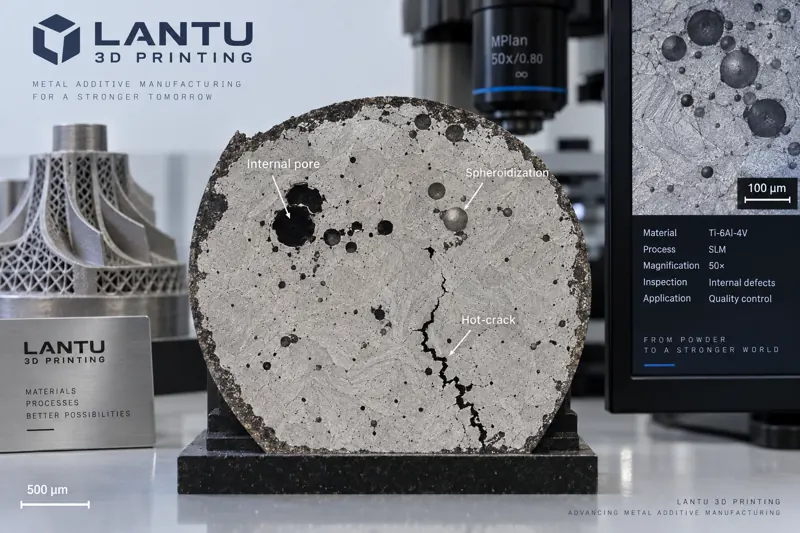
Introduction: Why Defect Analysis in Metal 3D Printing Is the First Threshold for Mass Production
Metal additive manufacturing (SLM/DMLS) uses high-energy lasers to melt metal powder layer by layer, enabling parts to be manufactured directly with almost no need for molds. However, precisely because of the process nature of “layer-by-layer stacking,” the intense thermal fluctuations that occur within extremely short periods make balling, porosity, hot cracking, and warping deformation frequent defects. For companies pursuing stable batch delivery, defect analysis is not after-the-fact firefighting, but a front-end engineering capability that determines yield, lead time, and cost. Starting from the mechanisms of four typical defects, this article presents practical process suppression paths and process monitoring methods.
1. Balling Defects: A Surface Signal of Melt Pool Instability
Balling/Spheroidization refers to a defect in which a melt track that should spread continuously shrinks into a chain of bead-like metal spheres. Its root cause is that the laser energy is insufficient to fully wet the powder, or that oxide films in the powder cause surface tension to dominate. When the linear energy density is lower than about 0.3 J/mm, the melt pool cannot spread sufficiently; when the oxygen content in the atmosphere exceeds 1000 ppm, the balling rate increases significantly. Key suppression measures include controlling volumetric energy density within the range of 50–80 J/mm³, using fine powder with a particle size of 30–60 μm, and reducing the oxygen content of the protective atmosphere to below 500 ppm. For the titanium alloy Ti6Al4V, a typical combination of 200–280 W laser power, 800–1200 mm/s scanning speed, and 30 μm layer thickness can significantly reduce balling.
2. Porosity Defects: The Enemy of Density and Fatigue Life
Porosity can be divided into lack-of-fusion pores and gas pores. Lack-of-fusion pores originate from insufficient interlayer energy or excessive hatch spacing (more than 1.2 times the spot diameter), and appear as flattened shapes along the melt track direction in CT slices. Gas pores come from moisture adsorbed by the powder or entrained shielding gas, and are distributed in near-spherical shapes. For every 1% decrease in density, fatigue life may decline by 15%–30%. Process countermeasures include maintaining an overlap rate of 30%–50%, vacuum drying nylon/metal powder at 80°C for 4 hours before warehousing, and keeping the chamber oxygen content stable within 500 ppm. For critical load-bearing parts, 100% industrial CT sampling inspection is recommended, using 20–50 μm voxels to capture critical defects.
3. Hot Cracking: Fracture Caused by Thermal Stress Exceeding Material Ductility
Hot cracking is commonly seen in materials with high alloy content, such as Inconel 718, aluminum alloy AlSi10Mg, and maraging steel. Rapid cooling layer by layer produces a cooling rate of about 10⁶ K/s, and the huge thermal gradient induces liquation cracking at grain boundaries. There are three mitigation paths: first, preheat the substrate to 80–200°C to reduce the temperature gradient; second, optimize the scanning strategy by using chessboard island scanning with an island size of 5–10 mm combined with 67° rotation to break up heat accumulation; third, introduce 0.5%–2% grain-boundary strengthening elements or adjust the Ni/Al ratio for crack-sensitive alloys. It is worth noting that hot cracks often become visible only after support removal, so fluorescent penetrant testing should be completed before post-processing.
4. Warping and Residual Stress: Hidden Killers of Dimensional Stability
Warping deformation originates from residual stress generated when interlayer shrinkage is constrained. When the stress exceeds the bonding strength with the substrate, the edges of the part may curl upward or even peel off. Residual stress along the build direction can reach several hundred MPa and is a major cause of assembly dimensions exceeding tolerance. In engineering practice, it is controlled through three measures: substrate preheating to reduce gradients; contour-fill separated scanning to reduce edge concentration; and post-build stress-relief annealing at 500–650°C for 2 hours for titanium alloys, or hot isostatic pressing at 540°C for superalloys. For parts sensitive to dimensional chains, a finishing allowance of 0.1–0.3 mm should be reserved in the design, and CNC final machining should be used to ensure geometric tolerances.
5. Standardized Process for Defect Analysis: From Inspection to Closed Loop
A reproducible defect-analysis method should include four steps: first, establish a defect baseline through first-article CT and metallographic sectioning; second, collect melt pool infrared temperature and spatter images through process monitoring to identify abnormal layers in real time; third, build a defect-parameter mapping table that links balling/porosity/cracking to specific process windows; fourth, perform process capability analysis using tools such as Minitab, with Cpk ≥ 1.33 as the release threshold for mass production. When the Cpk of a batch falls below 1.0, a parameter review should be triggered immediately instead of allowing the batch to flow into the next process. This closed loop turns defects from “occasional accidents” into “traceable indicators.”
Conclusion
Defects in metal 3D printing are not uncontrollable; they are predictable results of the coupling of energy, materials, and geometry. Balling is controlled through energy density and atmosphere management, porosity through overlap rate and powder management, hot cracking through preheating and scanning strategy, and warping through stress-relief annealing and allowance design. Only by moving defect analysis forward into the process qualification stage and forming a closed loop with CT, process monitoring, and Cpk control can companies truly keep yield in their own hands as they move from small-batch prototyping to mass production.
Submit a model, drawing, image or written notes. Engineers will review material, process, finishing and delivery based on actual use.