
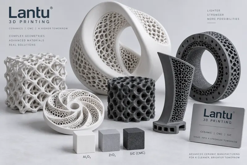
Introduction: Ceramics, Once Defined by Being “Difficult to Machine,” Are Being Redefined by Additive Manufacturing
Ceramic materials are known for high hardness, high-temperature resistance, corrosion resistance, and excellent electrical insulation. They play an irreplaceable role in aerospace, semiconductors, medical devices, and energy equipment. At the same time, ceramics are typical “difficult-to-machine” materials: they are hard and brittle, and conventional dry pressing, injection molding, or machining routes are often ineffective for complex geometries, with high tooling costs and slow iteration for small batches. Additive Manufacturing decouples “forming” from “sintering”: flowable feedstock is first stacked into a near-net-shape green body, and final ceramic performance is then achieved through high-temperature sintering. This makes internal channels, lattice structures, conformal cooling cavities, and other geometries that are impossible for conventional processes achievable. This article systematically reviews two mainstream ceramic 3D printing routes—photopolymerized ceramics and ceramic matrix composites (CMC)—and outlines the key engineering controls from slurry formulation to sintering and post-processing.
1. Photopolymerized Ceramics: The Three-Step SLA/DLP Route of “Slurry–Debinding–Sintering”
Photopolymerized ceramics, also known as Ceramic Stereolithography, are currently among the highest-precision ceramic additive manufacturing routes. The core principle is to disperse ceramic powders—typically alumina Al₂O₃, zirconia ZrO₂, silicon nitride Si₃N₄, or hydroxyapatite HAp—into a photosensitive resin to prepare a high-solids ceramic slurry, usually with a solids loading of 40–60 vol%. Ultraviolet laser curing (SLA) or digital light projection (DLP) is then used to cure the material layer by layer into a “green body.”
There are three key engineering parameters: slurry solids loading and viscosity—higher solids loading reduces sintering shrinkage and increases density, but excessive viscosity makes recoating and blade spreading difficult; viscosity is typically controlled at 3–10 Pa·s at a shear rate of 10 s⁻¹; refractive index matching—the smaller the refractive index difference between ceramic powder and resin, the more uniform the UV penetration and curing depth, helping avoid uneven interlayer curing; layer thickness and exposure energy—layer thickness is usually 25–100 μm, and exposure energy density must match the slurry curing curve. Overexposure can cause overflow adhesion, while underexposure leads to insufficient interlayer bonding.
2. Debinding and Sintering: Shrinkage Compensation Is the Key to Success
The green body must undergo two thermal treatment steps to become a ceramic part. The first step is Debinding: organic resin is decomposed and removed in the 500–600 ℃ range at an extremely slow heating rate of 0.1–1 ℃/min. If the heating rate is too fast, rapid gasification of organics creates internal pressure, causing cracking or blistering. The second step is Sintering: alumina generally requires 1500–1650 ℃, zirconia requires 1400–1550 ℃, and silicon carbide requires temperatures above 1900 ℃, unless reaction sintering or liquid-phase sintering aids are used to reduce the required temperature.
Sintering is accompanied by significant volume shrinkage, with linear shrinkage commonly in the range of 15%–25%. Therefore, shrinkage compensation is a core engineering step in ceramic 3D printing. Parts must be scaled up isotropically—or anisotropically after calibration—during the modeling stage, and the actual shrinkage curve of each specific furnace batch must be calibrated using standard test coupons. If shrinkage compensation is ignored, dimensional deviations may reach ±3%–5%, far exceeding the typical ±0.5% requirement for precision ceramics.
3. Ceramic Matrix Composites (CMC): Printable High-Temperature Structures That Use Fibers to “Stop Cracks”
The fatal weakness of monolithic ceramics is brittleness: once a crack forms, catastrophic fracture can occur. Ceramic Matrix Composites (CMC) introduce continuous fibers, such as carbon fiber C/C or silicon carbide fiber SiC/SiC, or whiskers/short fibers into a ceramic matrix. Cracks are deflected, bridged, and pulled out at the interface, transforming “brittle fracture” into “non-brittle failure” and increasing fracture toughness by several times.
There are currently three main additive manufacturing routes for CMC: (1) Continuous fiber route—SiC fiber tows are pre-impregnated and synchronously laid down by the print head while being infiltrated with ceramic precursor, forming the structure layer by layer; this is suitable for load-bearing components. (2) Precursor Infiltration and Pyrolysis (PIP) route—a green body containing precursor is first printed by photopolymerization or binder jetting, then densified through repeated “infiltration–pyrolysis” cycles to fill pores. Its drawbacks are many cycles, long lead time, and difficult shrinkage control. (3) Reactive Melt Infiltration (RMI) route—a carbon-based skeleton is printed and infiltrated with molten silicon, which reacts in situ to form a SiC matrix. This route offers high density and short cycle time, but residual free silicon may affect high-temperature performance.
It should be emphasized that CMC additive parts used for long-term high-temperature service must be evaluated for the fiber/matrix interface, residual porosity with a target of <3%, and oxidation protection coatings. Their process chain is much longer than that of ordinary photopolymerized ceramics.
4. Material and Application Selection: From Alumina to SiC/SiC
Different ceramic materials correspond to different application boundaries: zirconia combines high strength and biocompatibility, making it suitable for dental prostheses and orthopedic implants; alumina offers strong cost performance and good insulation, making it suitable for electronic ceramic substrates and wear-resistant parts; silicon nitride has excellent thermal shock resistance and is suitable for bearing balls, turbocharger rotors, and other high-temperature, high-load components; SiC/SiC composites are designed for the most demanding high-temperature structures, such as aero-engine combustion chambers, turbine blades, and nuclear cladding.
The selection logic should follow the “performance–process–cost” triangle: first identify candidates based on the required upper limits of material performance, such as temperature resistance, toughness, thermal conductivity, or insulation; then evaluate whether mature printable slurries or CMC processes are available for those materials; finally calculate unit cost and delivery time. Designers should avoid directly copying the design intent of metal parts into ceramics—ceramic wall thickness, fillets, and hole-edge chamfering strategies are completely different from those used for metals.
5. Additive-Oriented Ceramic Design Rules
Ceramic additive design must serve both forming and sintering stages: wall thickness is recommended to be no less than 0.8–1.5 mm, as overly thin walls are prone to cracking during debinding due to stress from organic removal; fillets and transitions should be made as large as possible to avoid stress concentration and sintering crack initiation at sharp corners; internal channels are difficult to fully drain in photopolymerization routes, so drainable structures and outlet holes are recommended; for support strategy, ceramic parts are relatively heavy, so supports for overhangs must be sufficiently dense, and green-body sanding after support removal is required to prevent support marks from becoming crack origins.
6. Post-Processing and Quality Verification
Sintered ceramic parts usually require precision finishing and verification. Diamond grinding and polishing are used to finish mating surfaces. Hot isostatic pressing (HIP) can further close internal residual pores and improve density and strength. Quality verification relies on industrial CT to detect internal pores and cracks, the Archimedes method to measure density, three-point or four-point bending tests to measure strength, fracture toughness K_IC testing, and thermal shock cycling tests. For medical and aerospace applications, dedicated verification such as biocompatibility or high-temperature fatigue testing is also required.
Conclusion
The value of ceramic 3D printing is not in “replacing” mass forming in the traditional ceramics industry, but in using the geometric freedom of additive manufacturing to enable structures that conventional processes cannot achieve: internal conformal channels, lightweight lattices, gradient materials, and complex load-bearing CMC parts. Successful implementation depends on three factors: first, calibration of slurry solids loading and shrinkage compensation for photopolymerization routes; second, strict control of the fiber/matrix interface and porosity in CMC routes; third, designing the part together with sintering shrinkage, debinding venting, and post-processing verification as one integrated process chain. For companies seeking to expand high-performance material capabilities, ceramic additive manufacturing is not simply an equipment purchase, but a new process system requiring coordination among materials, processes, and inspection.
Submit a model, drawing, image or written notes. Engineers will review material, process, finishing and delivery based on actual use.