
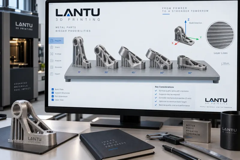
Introduction: The First Step That Determines a Part’s “Fate”
In metal laser powder bed fusion (LPBF) or stereolithography (SLA), simply changing the orientation of the same model file inside the build chamber can significantly alter tensile strength, dimensional accuracy, support volume, and unit cost. In engineering practice, print orientation is often selected casually after modeling and before slicing, yet it directly defines the boundaries of all subsequent process windows. This article presents a practical decision-making method for optimizing print orientation and placement from four perspectives: anisotropy, supports, accuracy, and cost.
1. Anisotropy: Directional Dependence of Mechanical Properties
Metal parts produced by selective laser melting (SLM) exhibit clear anisotropy. Taking 316L stainless steel as an example, tensile strength along the build direction, or Z direction, is typically about 5%–12% lower than in the horizontal XY direction, while elongation can differ by more than 20%. The root cause is that columnar grains formed during layer-by-layer melting and solidification grow along the heat flow direction. When the load direction is perpendicular to the interlayer bonding plane, incomplete fusion defects and grain boundaries between layers become preferential paths for crack propagation.
Therefore, for critical areas subjected to primary tensile stress or fatigue loads, the principal stress direction should be kept as parallel as possible to the powder spreading plane—in other words, “keep the layer lines away from the load direction.” For cantilevers and slender shaft-like parts, placing the long axis at roughly 45° to the build plate is often a compromise between strength and support volume, rather than the orientation with the absolute highest strength. This should be judged together with finite element analysis results and should not be generalized.
2. Support Structures and Removability
Orientation directly determines the area and angle of overhanging surfaces. In engineering practice, overhangs exceeding 45° relative to the build plate are generally considered areas that require support. Laying a part flat can reduce its overhanging projection in the Z direction, but it also increases the contact cross-section with the build plate, resulting in higher thermal stress and supports that are harder to remove. For internal channels, conformal cooling passages, and other structures where supports cannot be mechanically removed, priority should be given to orienting the channel axis close to vertical, so that supports inside the passage can be removed by flushing, erosion, or cold extraction.
It is important to note that supports are not merely “space fillers”; they also serve as heat dissipation paths. Dense supports accelerate local cooling and reduce deformation, but they also increase post-processing time. Orientation optimization must balance both “printability” and “post-processability,” rather than focusing only on support volume.
3. Dimensional Accuracy and Deformation
The accumulation of interlayer thermal stress can cause warping after a part is removed from the build plate. When long strip-shaped parts are oriented along their length, parallel to the recoater travel direction, shrinkage is concentrated in a single direction, and warpage is usually smaller than when they are oriented along their width. For precision-sensitive features such as mating surfaces and guide rail surfaces, the surface should be placed vertical or nearly vertical to the build plate to prevent it from becoming a large-area overhanging thin wall during printing.
In addition, placement within the build chamber also affects accuracy. Areas near the edge of the build plate have less uniform gas flow and temperature fields, and dimensional deviations are usually greater than in the central area. During batch nesting, parts with the strictest tolerance requirements should be placed near the center of the chamber and kept away from edge distortion zones of the laser optical path.
4. Cost and Capacity: The Economics of Orientation
Orientation affects unit cost through three variables: build height, support volume, and post-processing time. For the same part, stacking along the Z direction increases the number of layers and total build time, directly raising machine-hour cost. A reasonable flatter orientation can significantly reduce build height and shorten the unit production cycle. In batch production, nesting and height matching among multiple parts can increase Z-axis space utilization in the build chamber from 40% to more than 70%.
However, “lower is better” is not always true. Excessive flattening can introduce large support areas and more grinding time. In engineering practice, the orientation objective is usually to minimize the combined value of machine-hour cost, support post-processing cost, and scrap loss, rather than optimizing any single factor in isolation.
5. Assisted Decision-Making: From Experience to Computation
Mature orientation optimization has evolved from relying on “master craftsman experience” to using computable workflows. Anisotropic material models and thermomechanical coupled simulation are used to predict deformation, while support volume, build height, and maximum overhang angle serve as constraints for multi-objective optimization. Some CAM software already includes built-in “automatic orientation” functions that output candidate orientations and rank them by an overall score. It is recommended to limit the candidates to 3–5 options, then manually review them using a scoring table covering four items: strength direction, support volume, Z-height, and post-processing difficulty. This helps avoid algorithm-generated solutions that are printable but impossible to remove supports from.
6. Common Misconceptions and Checklist
Submit a model, drawing, image or written notes. Engineers will review material, process, finishing and delivery based on actual use.