
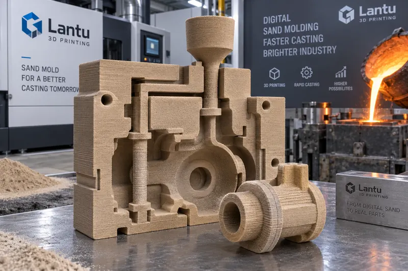
Introduction: Why Rapid Casting Is Regaining Attention in Manufacturing
In equipment manufacturing, energy equipment, and construction machinery, the development of large castings has long been constrained by a structural contradiction: wooden patterns and metal tooling typically require 4 to 10 weeks to manufacture, while design iterations for the casting itself often take only a few days. When an R&D team wants to validate a new water jacket layout or rib configuration within two weeks, the conventional tooling route simply cannot respond. More practical pressure comes from small-batch and spare-part scenarios: demand for a non-standard cast iron spare part on a production line may be only 10 to 30 pieces per year, yet the tooling cost must be allocated to every part, making the unit price unacceptably high.
Binder jetting sand mold 3D printing has matured precisely in this gap. It does not print the final part itself; instead, it prints the sand molds and cores used for pouring, reducing the tooling stage from weeks to days. For a full-lifecycle platform such as lantu3D, which delivers from blueprint to physical part, the value of sand mold printing is not only speed. It also gives casting, one of the oldest manufacturing processes, renewed digital iteration capability: when the geometry changes, the sand mold can simply be reprinted, without any sunk cost in tooling assets.
1. Process Principles and Key Parameters of Binder Jetting Sand Molds
The basic binder jetting process is as follows: a recoating roller spreads a layer of foundry sand 0.25 to 0.4 mm thick across the build box; the printhead selectively jets binder according to the cross-sectional profile; the binder reacts with the curing agent on the surface of the sand grains, crosslinking and bonding that layer into shape. The unprinted areas remain loose and act as natural support. After one layer is completed, the build box descends by one layer thickness, and sand spreading and jetting are repeated until the entire sand mold is stacked.
Four core parameters determine whether a sand mold is usable. The first is layer thickness, commonly in the range of 0.28 to 0.5 mm: the thinner the layer, the smaller the stair-stepping effect on the sand mold surface and the better the casting surface quality, but printing time increases proportionally. For non-functional cosmetic surfaces, 0.4 mm is usually sufficient. The second is binder saturation, meaning the percentage of the sand mold pore volume occupied by the jetted binder, generally controlled between 20% and 35%. When saturation is below 18%, the sand mold strength is insufficient, and edges are prone to collapse during removal and handling; above 40%, gas generation rises significantly, and invasive porosity can easily form inside the casting during pouring. The third is curing time. Initial crosslinking of the binder must be ensured between layers; spreading the next layer too quickly can cause interlayer shear slip, appearing as offset lines on the sidewalls of the sand mold. The fourth is sand mold strength. Room-temperature tensile strength is generally required to reach 1.2 to 2.5 MPa, while residual strength at high temperature, above 800 degrees Celsius, should be controlled within a suitable range. If residual strength is too high, casting shrinkage is restrained, resulting in hot tearing.
2. Selection Logic for Sand and Binder Systems
The material system for sand mold printing is not complex, but selection directly determines casting quality. In terms of base sand, there are three main categories: silica sand, artificial ceramic sand such as ceramic beads, and zircon sand. Silica sand has the lowest cost, with a coefficient of linear expansion of about 12×10⁻⁶/K. When pouring thin-walled complex parts, phase-transformation expansion can easily cause veining and sand inclusion defects. Ceramic sand has a coefficient of linear expansion of about 5×10⁻⁶/K, high sphericity, and refractoriness above 1700 degrees Celsius. It is suitable for stainless steel and high-temperature alloy castings, but its price is about 4 to 6 times that of silica sand. Zircon sand offers the best refractoriness and chilling capability and is mostly used for local chills or inserts at critical hot spots.
Binder systems are mainly based on furan resin and phenolic resin. Furan resin cures quickly at room temperature and provides high sand mold strength, making it suitable for one-off and small-batch rapid delivery. However, it generates more gas during pouring and must be paired with proper venting design. Phenolic systems, including inorganic binders, produce significantly less gas and deliver more stable casting surface quality, so they are often used for thin-walled parts that are sensitive to porosity. The trade-off is slightly lower sand mold strength and slower curing. Inorganic binders have advanced substantially in recent years; in some systems, gas generation has been reduced to less than 30% of organic systems, with particularly strong performance in aluminum alloy castings.
It is worth emphasizing that resin addition should follow a lower-limit principle. On the premise of meeting mold removal strength, the resin addition should be controlled within 0.8% to 1.5% by sand weight. For every 0.1 percentage point reduction, the risk of casting porosity shows a measurable decrease. This is also why load paths must be evaluated during the sand mold design stage: unnecessary bulky sand sections are not only wasteful, but also continuously release gas.
3. Sand Mold Design: From Casting Drawing to Printable Sand Mold
The greatest benefit released by sand mold 3D printing is geometric freedom, but freedom does not mean arbitrariness. At least four tasks must be addressed when designing a sand mold.
The first is parting and removal feasibility. Although printing eliminates the hard constraint of draft angles, the sand mold still needs human-machine handling when being removed from the build box, depowdered, and transported to the core-setting station. Narrow slots with an internal depth-to-width ratio greater than 4:1 are very difficult to depowder. A practical approach is to split deep cavities into stackable sand core modules and use locating tenons and grooves to ensure assembly accuracy.
The second is systematic venting channel layout. Binder-bonded sand molds have better permeability than conventionally compacted sand molds, but this cannot replace active venting. Vent holes with diameters of 6 to 12 mm should be placed at the highest points of the sand mold and above hot spots, with hole spacing controlled between 80 and 150 mm. Venting core rods or hollow channels should be designed inside cores to guide gas generated by heated cores out of the sand mold. A typical consequence of insufficient venting is large areas of subsurface porosity appearing on the top surface of the casting, which become exposed after grinding and are extremely costly to repair.
The third is accurate specification of shrinkage and machining allowance. Sand mold printing does not change the shrinkage rate of the alloy itself: gray cast iron is about 1.0%, ductile iron about 0.6% to 0.8%, aluminum alloy about 1.0% to 1.3%, and cast steel about 1.5% to 2.0%. This can be compensated in the casting model. The real variable is the dimensional deviation caused by sand mold printing accuracy, which can typically be controlled within ±0.3 mm/m. In terms of machining allowance, printed sand castings have good dimensional stability, allowing 1 to 2 mm less allowance than conventional sand castings and directly reducing subsequent machining time.
The fourth is coordination between the gating system and risers. 3D printing makes conformal gating systems and point gates easier to implement. Gates can be placed directly near hot spots to achieve a more rational feeding sequence. It is recommended to run a solidification simulation first, confirm the locations of isolated liquid regions, and then determine riser dimensions, avoiding the waste of complex-geometry advantages through overly conservative riser design.
4. Post-Processing, Pouring, and Quality Verification
The processing flow after sand mold printing is equally critical. During depowdering, industrial vacuuming must be used together with soft tools; striking with hard objects is prohibited to avoid damaging the edges and corners of the sand mold. After depowdering, the entire sand mold should undergo secondary curing. Furan systems are usually left at room temperature for 4 to 8 hours or treated in a drying oven at 60 to 80 degrees Celsius for 1 to 2 hours. Applying a coating is optional but strongly recommended: a 0.2 to 0.4 mm layer of alcohol-based or water-based coating can significantly improve casting surface finish while preventing molten metal from penetrating the gaps between sand grains and causing mechanical burn-on. The coating must be thoroughly dried; residual moisture will vaporize instantly during pouring and cause widespread porosity.
The focus during pouring is temperature and speed. Because sand molds have lower thermal conductivity than metal molds, pouring temperature can follow conventional sand casting standards. However, special attention must be paid to the match between gas generation and filling speed. Excessively fast filling can trap gas inside the sand mold. It is recommended to verify filling time in simulation, typically controlling thin-walled parts at 8 to 20 seconds and large, thick parts at 30 to 60 seconds.
Quality verification should establish three levels of inspection: after printing, perform 3D scanning or key-point measurement of critical sand mold dimensions and record the results; before pouring, carry out visual inspection and tap testing of the sand mold, as a dull sound usually indicates local incomplete curing; after casting cleaning, perform dimensional inspection according to the drawing and necessary non-destructive testing. The first article must undergo a complete dimensional report and sectioning verification before small-batch production can begin.
5. Application Scenarios and Cost Boundaries
Sand mold 3D printing is not economical in every scenario. Its economic advantages are concentrated in three categories: one-off and small-batch production, where annual demand below roughly 200 pieces is almost always better than making tooling; castings with complex geometries that would require multiple sand cores in conventional processes, where the more cores required, the more tooling and assembly labor the printing solution can save; and R&D iteration stages, where design change costs are close to zero. Conversely, when the part structure is extremely simple and annual demand exceeds several thousand pieces, conventional tooling or permanent molds still deliver lower unit cost.
Lead time is another benefit that is often underestimated. Taking a cast iron housing of medium complexity as an example, the conventional route usually takes 6 to 9 weeks from drawing to first article. With sand mold printing, mold printing takes 1 to 2 days, curing and coating take 1 day, and pouring and cleaning take 3 to 5 days, compressing the overall schedule to 7 to 10 working days. In scenarios where spare-part shortages stop a production line, this difference directly translates into avoided downtime losses.
Conclusion
The essence of binder jetting sand mold 3D printing is to replace the least flexible link in the casting process, tooling manufacture, with a programmable digital step. Its technical barrier does not lie in the equipment itself, but in the coordinated control of four groups of variables: gas generation, venting design, shrinkage compensation, and sand mold strength. For manufacturers, the correct path is to first define the process window using solidification simulation and sand mold strength data, and then use geometric freedom to solve problems that traditional processes cannot solve, rather than simply printing old drawings as they are. In practice, lantu3D consistently manages it as a complete chain from design blueprint to physical delivery. The sand mold is only one link; what is truly delivered is a physical part that is assemblable, verifiable, and traceable.
Submit a model, drawing, image or written notes. Engineers will review material, process, finishing and delivery based on actual use.