
Introduction: Overlooked Sources of Downtime
In additive manufacturing workshops, equipment reliability is frequently discussed, yet the actual causes of production stoppages often originate outside the machines themselves. A fluctuation in inert-gas purity may cause oxygen content in an entire batch of titanium parts to exceed specification; cooling-water temperature drift may trigger a laser interlock shutdown; increased moisture in compressed air may cause powder transfer lines to cake. The root causes of these events lie not in the printer, but in the utility and auxiliary systems that supply gas, water, power, and dust extraction. For 3D printing service operations focused on high-mix, low-volume production, the cost of a single unplanned utility-system shutdown is often greater than the loss caused by an individual machine failure.
1. Utility System Boundaries and Allocation of Responsibilities
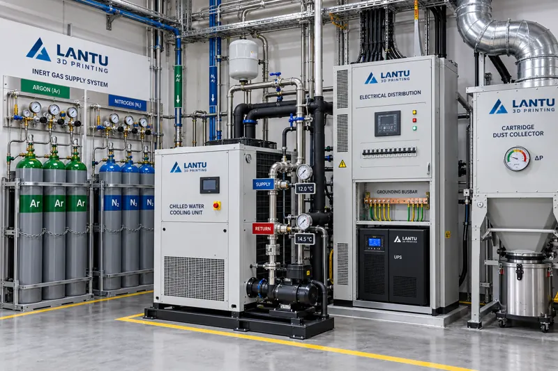
Utility systems in metal additive manufacturing workshops typically comprise four main lines: inert-gas supply (argon and nitrogen), recirculating cooling water, power distribution and grounding, and dust collection and exhaust-gas treatment. These systems correspond respectively to risks involving build quality, optical and electrical stability, and personnel and environmental safety.
The most common mistake in allocating responsibilities is to outsource utility systems entirely to plant facilities teams while process departments focus only on printing parameters. In practice, inert-gas purity is a process input and should be incorporated into process procedures; recirculating cooling-water temperature and conductivity are equipment operating conditions and should be included in equipment inspections; dust-collection differential pressure is a safety interlock condition and should be managed under EHS procedures. When boundaries are unclear, alarms sound without an owner, and records are created without analysis.
2. Inert-Gas Supply: Purity, Pressure, and Continuity
For reactive metals such as titanium alloys, aluminum alloys, and nickel-based superalloys, oxygen concentration in the build chamber generally must be controlled below 1,000 ppm. Some aerospace components require levels as low as 500 ppm or lower. This requires source-gas purity of at least 99.996%, with no leakage or dead volume in the delivery piping.
Three indicators require particular attention in engineering practice. The first is purity and dew point: when supplied through cylinder banks or liquid-argon vaporization systems, the dew point should be below -60°C. Excessive moisture can decompose into hydrogen in the high-temperature melt pool, producing hydrogen porosity. The second is supply-pressure stability: gas flow differs substantially between purging and maintenance stages during a build. A pressure-regulating valve should be installed downstream of the buffer tank to control pressure fluctuation within ±0.05 MPa, preventing passive extensions of purging time due to insufficient flow. The third is supply continuity: replacing a single cylinder creates a risk of pressure drop. Dual cylinder banks or automatic manifold switching should be used, with an interlock in the switching logic that prevents a new powder layer from being started during the cylinder-change window.
For documentation, oxygen-concentration curves should be retained by batch rather than recording only the final value. The curve profile provides greater diagnostic value than a single reading: if oxygen concentration drops rapidly during the first 300 layers and then stabilizes, purging is adequate; if periodic spikes occur during the build, the cause is usually minor leakage at pipe joints or switching-valve operation.
3. Recirculating Cooling Water: Temperature, Flow, and Water Quality
Lasers, galvanometer scanners, diffusion pumps, and cold plates each have different temperature-sensitive ranges for cooling water, but all share one requirement: stable temperature rather than low temperature. For example, inlet water for a fiber laser is generally set to 22 ±2°C. When temperature drift exceeds ±3°C, electro-optical conversion efficiency and output-power consistency decline, directly causing variation in melt depth.
A less visible issue is water quality. Higher conductivity can cause scale formation and electrochemical corrosion. As cooling-channel cross-sectional area decreases, localized overheating develops and eventually triggers flow alarms. Conductivity should be maintained below 500 μS/cm, and filter differential pressure and internal pipe-wall condition should be checked quarterly. Workshops operating over the long term should use closed-loop circulation with plate heat exchangers to avoid contaminants and algae associated with open cooling towers.
Differences between winter and summer operating conditions must also be included in validation. Cooling capacity declines during hot summer conditions, so ambient conditions should be incorporated into the boundary conditions of equipment capability validation. A standard test part should be verified under worst-case conditions rather than calibrating only during comfortable seasons.
4. Power Quality and Grounding: Underestimated Variables in Accuracy
Precision motion platforms, galvanometer drives, and control systems are sensitive to power quality. Voltage sags, harmonic distortion, and instantaneous outages can cause communication interruptions or trajectory deviations. Minimum engineering requirements include providing online UPS systems for critical equipment, with backup time sufficient to cover normal shutdown procedures; supplying lasers and control systems separately to prevent large-load switching from disturbing a shared bus; and maintaining grounding resistance below 4 Ω with equipotential bonding to prevent ground loops from introducing measurement noise.
One typical failure involved periodic surface patterns appearing on parts being printed whenever powder-sieving equipment was started. Investigation found that the sieving motor and printer shared the same power circuit. The voltage dip during startup and shutdown was detected by the galvanometer drive board, triggering position re-homing. The patterns disappeared after the power supplies were separated. Such issues are rarely addressed in equipment manufacturers' manuals and can only be prevented in advance through proper workshop power-distribution planning.
5. Dust Collection and Exhaust Treatment: Differential Pressure as a Health Indicator
The dust-collection system for metal-powder handling units is not merely an environmental-control facility; it is also part of the safety interlock system. Filter differential pressure is the most direct monitoring variable. A newly installed filter typically has a differential pressure of 200-500 Pa. When it rises to 1,200-1,500 Pa, reduced airflow causes insufficient negative pressure, allowing dust to escape from hood openings while the fan operates under sustained high load.
Differential pressure should be included in routine inspections and linked to cleaning cycles, rather than replacing filters on a fixed calendar schedule. For dust collectors handling reactive metal powders, attention must also be paid to filter-media conductivity, antistatic treatment, and the containment of dust-discharge operations. Open dust discharge is one of the most frequently overlooked dust-cloud risks in these workshops. Where exhaust treatment includes activated-carbon adsorption units, saturation should be determined by cumulative operating time or inlet-to-outlet concentration difference, not by odor.
6. Moving from Reactive Repair to Condition-Based Management
Utility-system management maturity can be divided into three levels. The first is repair after failure, characterized by failure records without trend data. The second is periodic inspection, characterized by checklists but thresholds based on experience. The third is condition-based management, characterized by defined control and alarm limits for every key parameter, automatic containment actions when limits are exceeded, and monthly trend reviews.
The cost of moving to the third level is not high. The core work consists of three actions: establish a parameter register for gas supply, cooling water, power distribution, and dust collection, with clear control limits and accountable owners; connect alarms for key parameters to workshop duty-response procedures instead of merely recording them on paper forms; and conduct a monthly review of limit-exceedance events to determine whether setpoints are unreasonable or system capability is inadequate. Once these actions are implemented, unplanned downtime caused by utility systems can typically be reduced significantly within two to three quarters.
Conclusion
The competitiveness of a 3D printing workshop does not depend solely on the printing equipment itself. Inert-gas purity and continuity, recirculating-water temperature and quality, power quality and grounding, and dust-collection differential-pressure management together form the foundation of build stability. Managing these four utility lines as process input conditions rather than facility-support matters is an essential step for high-mix, low-volume additive manufacturing operations to progress from simply being capable of production to delivering reliably. For platforms such as lantu3D that cover the entire process from design to physical delivery, standardizing utility conditions is likewise part of the commitment to consistent delivery.
Submit a model, drawing, image or written notes. Engineers will review material, process, finishing and delivery based on actual use.