
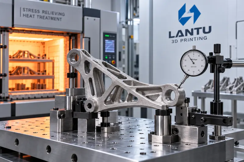
Introduction: Deformation Is the Final Mile of Additive Manufacturing Delivery
In metal and polymer additive manufacturing projects, what truly blocks first-time delivery is often not the printing itself, but the shape after printing. A 400 mm-long aluminum alloy bracket may meet dimensional requirements immediately after printing, yet warp by 1.8 mm after stress-relief annealing. A thin-walled titanium alloy housing may spring back after wire-cut removal, increasing the assembly surface gap from 0.2 mm to 1.1 mm. Such issues are extremely common in industrial practice: the internal stress in a part never truly disappears; it is released the moment constraints are removed. Deformation correction and dimensional compensation are methods for bringing this physical reality into an engineering-controlled range. In full-lifecycle delivery, lantu3D treats this step as an independent process rather than a remedial action after print failure.
1. Where Deformation Comes From: Thermal Stress, Constraints, and Phase Transformation
During laser powder bed fusion, the local temperature of the melt pool can exceed 1600°C, while the adjacent powder bed remains at 150–200°C. This extremely high temperature gradient causes non-uniform shrinkage between the solidified layer and the substrate, generating residual stress. When the stress exceeds the yield strength of the material at that temperature, plastic deformation occurs; when it exceeds the interface bonding strength, interlayer cracking or detachment from the build plate may occur. In addition, solid-state phase transformations during cooling in maraging steels and titanium alloys cause volume changes, while crystallization shrinkage in polymers also contributes to dimensional deviation. In engineering practice, deformation is usually divided into three categories by source: overall warping caused by thermal gradients, local collapse caused by insufficient structural stiffness, and springback caused by constraint release after cutting and support removal. These three require different correction methods, and treating them as the same problem is the root cause of many rework cycles.
2. Counter-Deformation Design: Using Pre-Deformation to Offset Deformation
Counter-deformation is one of the most economical methods—it does not add process steps, but applies geometric pre-compensation at the model stage. The approach is to obtain the deformation field through simulation or historical data, then offset the model in the opposite direction of the deformation. For example, if measurements show that the middle of a beam warps upward by 1.2 mm, that area is pressed downward by 1.2 mm during modeling. Three points require attention in practice. First, the counter-deformation value must come from measured data using the same equipment, the same material batch, and the same build orientation; applying data across different machines can result in errors of more than 40%. Second, counter-deformation changes the distribution of machining allowance, so datums and machining allowances must be marked in the model at the same time to avoid insufficient stock during finishing. Third, for thin-walled and long-span structures, simple linear offset is often insufficient and must be combined with local ribs or process supports. The success of counter-deformation depends on a data closed loop. It is recommended to establish a deformation log for each typical structure, recording batch, orientation, heat treatment regime, and final deviation.
3. Process Suppression: Supports, Orientation, and Scanning Strategy
The cost of correction is far higher than that of suppression. Reducing residual stress during printing mainly depends on three paths. First, build orientation: keeping large flat surfaces as parallel to the build plate as possible and reducing overhanging areas can significantly reduce angular deformation accumulated layer by layer; at the same time, large-area cross-section changes should be prevented from occurring at the same height. Second, support design: block supports should provide both heat conduction and anchoring, with the contact area controlled within a reasonable range to prevent local overheating while ensuring complete constraint before cutting. Third, scanning strategy: island scanning, interlayer rotation of 67°, and appropriate preheating—150–200°C build-plate preheating for aluminum alloys, and 200–500°C for titanium alloys depending on the equipment—can all effectively reduce peak stress. Equipment stability is equally critical. Galvanometer zero drift and energy attenuation caused by contamination of the protective lens can cause deformation in the same batch of parts to diverge. Therefore, process suppression must be based on controlled equipment condition.
4. Thermal and Mechanical Straightening: Process Windows and Risk Control
When deformation has already occurred, the choice of correction process depends on the material and structure. Thermal straightening is performed during stress-relief annealing or solution treatment by applying constraints to the part with tooling, allowing creep relaxation at high temperature to fix the shape. Its advantage is that stress relief and correction are completed in one step; its disadvantages are high tooling cost and the need for a precise understanding of the material’s creep behavior at that temperature. Mechanical straightening applies local plastic deformation at room temperature through three-point bending, rolling, or dedicated tooling. It is efficient but requires material ductility. High-strength aluminum alloys and titanium alloys have a very narrow straightening window at room temperature, and excessive correction can introduce microcracks. The straightening process must follow three principles: measure before applying force, load in multiple steps with each step not exceeding the allowable plastic strain, and perform non-destructive testing again after straightening to confirm that no new defects have been introduced.
5. Dimensional Compensation and the Digital Compensation Closed Loop
Modern production lines increasingly prefer to move correction upstream into digital compensation: 3D scanning is used to acquire the actual geometry of a part, point-cloud comparison is performed against the original model to obtain the deviation distribution, and the deviation is then mapped back to the next model or printing parameters. The key to this closed loop is measurement credibility—the scanning resolution should be better than one-fifth of the target tolerance, and the registration datums must be consistent with the design datums; otherwise, the compensation itself becomes a new source of error. For batch parts, it is recommended to conduct full-dimensional scanning on the first 3–5 parts to establish compensation coefficients, then switch to sampling inspection of key features after stabilization. Compensation model updates must include version management and change records to avoid mixing different compensation coefficients across batches. In project delivery, lantu3D typically standardizes this process as: printing, heat treatment, scanning, comparison, compensation, and re-verification, with traceable records at every step.
6. Verification and Release After Straightening
Completion of correction does not equal qualification for release. A complete release evidence chain should include measurement reports for critical dimensions, including the measurement system and gauge status; comparison records before and after deformation correction; non-destructive testing results to determine whether internal defects expanded due to correction; and, when necessary, mechanical property sampling or verification specimen testing. For regulated industries such as aerospace and medical, the correction process itself must be validated as a special process, including process specifications, operator qualifications, equipment capability, and record retention requirements. Companies should also note that if a corrected part has insufficient machining allowance, welding repair or reprinting should be prioritized rather than forced assembly.
Conclusion
The core of deformation correction and dimensional compensation is to transform uncontrollable physical release into measurable, predictable, and closed-loop engineering variables. The priority should be: first use orientation and supports for suppression, then use counter-deformation design for compensation, and only finally apply thermal or mechanical straightening. At the same time, scanning comparison should be used to establish a compensation closed loop, and complete verification evidence should be used for release. Incorporating this step into process documentation rather than treating it as a temporary remedy is the dividing line between additive manufacturing for prototyping and additive manufacturing for batch delivery.
Submit a model, drawing, image or written notes. Engineers will review material, process, finishing and delivery based on actual use.