
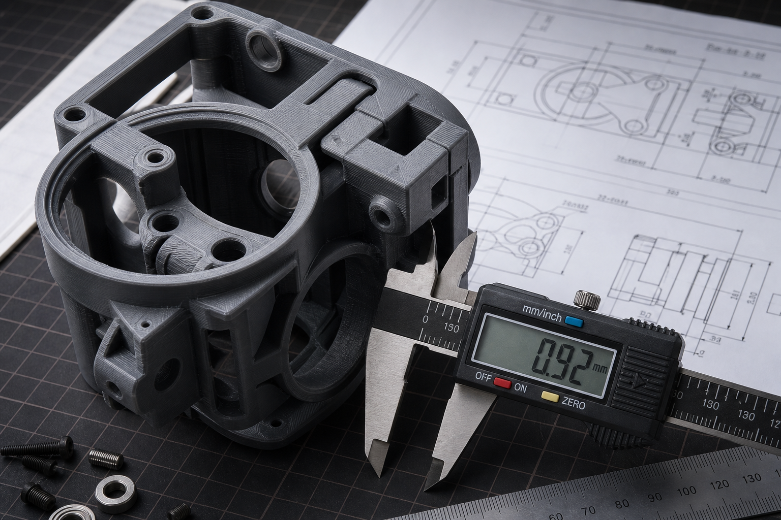
Basic Principles of 3D Printing Assembly Design
3D printing technology has brought unprecedented freedom to product design and manufacturing, but it has also posed new challenges for assembly design. Compared with traditional manufacturing (such as CNC machining and injection molding), 3D printing possesses unique characteristics in terms of precision, surface quality, and anisotropy, which directly influence choices in assembly design. A successful 3D printing assembly design requires full consideration of process characteristics during the design phase to avoid subsequent assembly difficulties or functional failures.
The core objective of assembly design is to ensure that parts can be assembled smoothly, maintain stable fit relationships during use, and facilitate maintenance and disassembly. For 3D printed parts, additional factors must be considered, such as the impact of print orientation on accuracy, the influence of support structures on surface quality, and the effect of post-processing on dimensions. Following the principles of "Design for Assembly" (DFA) can significantly improve assembly efficiency, reduce assembly costs, and enhance product quality.
Tolerance Design Principles and Process Selection
The precision characteristics of 3D printing processes vary depending on the technology. The accuracy of FDM processes is typically ±0.3-0.5mm (for a 100mm dimension), SLA/DLP photopolymerization processes can achieve an accuracy of ±0.1-0.2mm, SLS powder sintering processes have an accuracy of approximately ±0.2-0.3mm, and SLM metal printing can reach an accuracy of ±0.1mm. Designers need to set reasonable tolerances according to the precision capabilities of the selected process. Generally, 3D printed parts should not adopt overly tight tolerances (such as H7/g6), but rather looser tolerances (such as H8/h8 or H9/h9), while reserving sufficient allowance for adjustment.
When specifying tolerances, the influence of print orientation must also be considered. Most 3D printing processes offer higher accuracy in the XY plane (scanning plane) than in the Z direction (stacking direction); therefore, during design, dimensions with high accuracy requirements should ideally be placed within the XY plane. If a part requires high accuracy in the Z direction, changing the print orientation or using post-processing (such as finishing) can be considered to ensure accuracy. Furthermore, the accuracy of features such as circular holes and cylinders is typically lower than that of planar features, requiring special attention during design.
Gap Design Specifications
Clearance design is one of the most critical steps in assembly design. For 3D printed parts, due to limitations in surface roughness and dimensional accuracy, larger clearances are required compared to traditional manufacturing. For FDM printed parts, a clearance of 0.3-0.5mm is recommended for static fits (such as pin-shaft fits); for SLA/DLP printed parts, the clearance can be reduced to 0.15-0.3mm; and for SLS printed parts, a clearance of 0.2-0.4mm is recommended. These values are based on empirical data, and in practical applications, adjustments need to be made according to factors such as part size, fit length, and operating environment.
For moving fits (such as hinges and sliders), larger clearances are required. For moving fits in FDM printing, it is recommended to allow for a clearance of 0.5-1.0 mm to ensure smooth movement; for SLA/DLP printing, the clearance can be 0.3-0.6 mm; and for SLS printing, a clearance of 0.4-0.8 mm is recommended. If parts require post-processing (such as sanding or sandblasting), a post-processing allowance must also be factored into the clearance design, typically 0.1-0.3 mm, depending on the post-processing method and the amount of material removal.
Key Design Points for Moving Parts
3D printing technology is particularly suitable for manufacturing parts with complex moving mechanisms, such as hinges, gears, linkages, and cams. When designing moving parts, special attention must be paid to issues such as friction, wear, and maintaining clearances. For hinge design, it is recommended to adopt a "snap-fit" hinge structure, utilizing the elastic deformation of the material for assembly to avoid the use of metal pins. The rotational clearance of the hinge is recommended to be 0.4-0.8mm, and the wall thickness of the hinge should be no less than 2mm to ensure sufficient strength.
In gear design, the minimum gear module for 3D printing is limited by process resolution. For the FDM process, the minimum module is recommended to be no less than 0.5 mm; SLA/DLP processes can achieve 0.3 mm; and for the SLS process, a minimum module of no less than 0.4 mm is recommended. The backlash of the gears needs to be appropriately increased, typically to 0.1–0.2 times the module, to compensate for printing errors and thermal deformation. For high-speed or high-load gear transmissions, it is recommended to use metal inserts or subsequently replace with metal gears to improve wear resistance and transmission accuracy.
Selection of Fasteners and Connection Methods
There are various options for fastening and connecting 3D printed parts. The most direct method is to use standard metal fasteners (such as screws, nuts, and washers), which offers high reliability and ease of assembly, but requires designing appropriate threaded holes or through holes in the printed parts. For thermoplastic materials (such as PLA, ABS, and PETG), self-tapping screws can be driven directly into printed holes, with the hole diameter being 0.7 to 0.8 times the screw diameter. For metal 3D printed parts, it is recommended to use machined threads or threaded inserts to ensure connection strength.
In addition to mechanical fastening, methods such as adhesive bonding, welding, and snap-fit connections can also be adopted. Adhesive bonding is suitable for a variety of material combinations, but offers lower connection strength and is difficult to disassemble. Snap-fit connections are an area where 3D printing excels, allowing for the design of various complex snap-fit structures to achieve rapid assembly and disassembly. The design of snap-fits requires consideration of the material's elastic modulus and yield strength; the deformation of the snap-fit should not exceed 70% of the material's yield strain to avoid permanent deformation. The mating angle of snap-fits is typically 15-30°, and the release angle should be smaller than the assembly angle to facilitate disassembly.
Impact of Support Structures on Assembly Design
Support structures are an inevitable issue in 3D printing, particularly for FDM and SLA processes. Support structures leave marks on part surfaces, which can affect assembly accuracy. During the design phase, support structures should be avoided on assembly surfaces whenever possible. If unavoidable, the following strategies can be adopted: 1) Adjust the print orientation to position the assembly surface downwards (for FDM) or upwards (for SLA); 2) Leave a machining allowance of 0.2–0.5 mm on the assembly surface, and subsequently remove support marks through sanding or machining; 3) Utilize soluble support materials (such as PVA or HIPS) to minimize surface damage.
For SLS and SLM processes, since the powder itself can act as support, additional support structures are usually not required, resulting in better quality of assembly surfaces. However, the surface roughness of SLS parts is relatively high (Ra 6-12μm), and post-processing is still necessary if high precision is required for assembly surfaces. Furthermore, while SLM metal printing allows for overhang printing without supports, it is still recommended to add supports when the cantilever length exceeds 5mm to ensure dimensional accuracy and prevent thermal deformation.
Assembly Sequence and Modular Design
A significant advantage of 3D printed parts is the capability to implement highly integrated designs, consolidating multiple parts into a single unit to reduce assembly workload. However, excessive integration can also lead to increased printing difficulty, a greater need for support structures, and a higher rate of printing failures. Therefore, a balance must be struck between the degree of integration and manufacturability. Modular design is an effective strategy: decomposing a complex product into multiple relatively simple modules, printing each module independently, and then assembling them into the final product.
When planning the assembly sequence, the assembly and disassembly directions of the parts need to be considered. Each part should have at least one clear assembly direction with no obstacles in that direction. For components subject to frequent disassembly and reassembly, guide structures (such as chamfers and guide pins) should be designed to facilitate alignment and assembly. For precision assembly, "process datums" can be reserved during printing and removed after assembly to improve assembly accuracy.
Common Assembly Problems and Solutions
During the actual assembly process, 3D printed parts often encounter the following issues: 1) parts cannot be fitted—usually caused by insufficient clearance design or printing errors; the solution is to appropriately increase the clearance or adopt an iterative method of "trial assembly—sanding—re-assembly"; 2) parts fit too loosely—usually caused by excessive clearance or material shrinkage; the solution is to design adjustable structures (such as eccentric wheels, adjustment screws) or use filler materials (such as shims, glue); 3) jamming of moving parts—usually caused by excessive roughness on friction surfaces or uneven clearance; the solution is to improve surface quality (sanding, polishing) or adjust the clearance design.
To avoid these issues, it is recommended to conduct "prototype verification" before formal printing: use low-cost materials (such as PLA) to print a 1:1 assembly prototype to verify the feasibility and ease of assembly. If issues are identified, the design can be adjusted promptly to avoid wasting expensive engineering materials and printing time. Furthermore, establishing a standard parts library (such as standard screw holes, standard snap-fits, and standard hinges) can significantly improve design efficiency and assembly quality, while reducing design errors.
Submit a model, drawing, image or written notes. Engineers will review material, process, finishing and delivery based on actual use.