
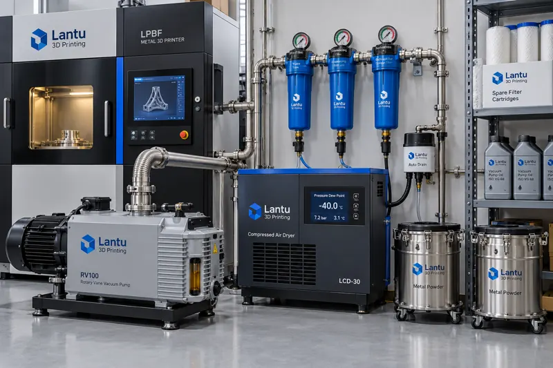
Why Auxiliary Fluid Systems Determine Equipment Availability
In metal laser powder bed fusion (LPBF) equipment, optical-path and mechanical failures are the most visible causes of downtime, while degradation in vacuum and compressed-air systems is almost invisible. Insufficient vacuum extends chamber purging time, causing oxygen concentration in the build chamber to remain in the 800–1500 ppm range for prolonged periods. Within this range, titanium and aluminum alloy powders show a clear increase in oxide inclusions and porosity tendency. Excessive moisture or oil in compressed air, meanwhile, manifests as sticking pneumatic valves, incomplete cylinder strokes, and buildup on the inner walls of powder-transfer lines, ultimately resulting in uneven recoating and missing layers. Such issues are often categorized in fault trees as “sporadic equipment abnormalities,” but the root cause is frequently nothing more than emulsified vacuum pump oil or a dryer dew point that has drifted by several tens of degrees Celsius.
Managing vacuum and compressed air as independent controlled systems, rather than treating them as utilities where “any available air will do,” is one of the most economical ways to raise equipment availability from 85% to above 95%. The main investment is in oil, filter elements, and dew point instruments; the return is avoiding scrapped batches and unplanned downtime.
1. Vacuum System Performance Baselines: Quantify First, Then Maintain
The health of a vacuum system cannot be judged simply by whether it can pull a vacuum. Three reproducible quantitative baselines must be established. The first is evacuation time: the time required to pump down from atmospheric pressure to the process-required base vacuum, typically 10–100 mbar for most LPBF machines. The new-machine baseline for equipment of the same model is generally 3–8 minutes; measured values exceeding 1.5 times the baseline should be considered abnormal. The second is ultimate vacuum: the lowest pressure attainable at the pump inlet after closing the isolation valve. Rotary vane pumps should remain stable at approximately 10⁻² mbar, while dry pumps are typically in the 10⁻¹–10⁰ mbar range. The third is pressure-rise rate, or leak rate: after reaching base vacuum, close the pump valve and record the chamber pressure rise over 10 minutes, then convert the result to mbar·L/s. Values exceeding the equipment manual limit—commonly 10⁻²–10⁻¹ mbar·L/s—indicate a leak point or outgassing source.
These three baselines should be collected during equipment acceptance and documented in maintenance records, then retested quarterly. Maintenance without baselines is limited to repairing failures after they occur. With baselines in place, intervention can begin when performance has degraded by 20%, at which point an oil or filter change is often sufficient.
2. Typical Vacuum Pump Degradation Mechanisms and Replacement Criteria
For oil-lubricated rotary vane pumps, the most common degradation mechanisms are oil emulsification and oil deterioration. Gas extracted from powder bed equipment carries fine metal dust and volatile organic compounds. If the inlet filter fails, dust enters the pump chamber and mixes with the oil, forming an abrasive mixture that both reduces ultimate vacuum and accelerates wear of the vanes and cylinder. Oil color and level are the primary criteria: fresh oil is transparent light yellow, while cloudiness, darkening, or milky-white emulsification signals that replacement is required. For production lines operating two continuous shifts, oil and the oil filter should be replaced every 1,500–2,000 hours; under heavy-duty conditions, the interval should be reduced to 1,000 hours.
A second degradation source is blockage of the exhaust filter, or oil mist separator. Once the filter element is saturated, exhaust backpressure rises, causing pump overheating and oil-mist leakage. Typical symptoms include pump temperature exceeding 90°C and visible oil mist at the exhaust outlet. Replacement criteria are exhaust pressure and visible oil mist, with replacement typically synchronized with oil changes or performed every 2,000–4,000 hours. A third source is the inlet filter element and pipeline seals: metal dust can form a dense layer on the filter surface and reduce pumping speed, while aging O-rings and flange seals can create microleaks. Such leaks are directly revealed by pressure-rise testing, and helium mass spectrometer leak detectors can locate individual flanges at the 10⁻⁶ mbar·L/s level.
The gas ballast valve is another frequently overlooked component. When handling condensable gases, such as residual solvent vapor after cleaning, the gas ballast must be opened; otherwise, vapor condenses in the pump chamber and mixes with the oil, becoming one of the main causes of oil emulsification. Maintenance procedures should explicitly specify that vacuum pumping within 30 minutes after cleaning requires gas-ballast operation for 20 minutes.
3. Compressed Air Quality: Set Classes Under ISO 8573-1 Instead of Relying on Intuition
Compressed-air issues have a mature classification framework in manufacturing: ISO 8573-1 classifies air quality by solid particles, water content in the form of pressure dew point, and oil content. For 3D printing facilities supplying pneumatic components and powder-transfer systems, typical engineering requirements are Class 2–3 for solid particles (particles ≤1–5 μm), Class 4 or better for pressure dew point (≤+3°C), and Class 1–2 for oil content (≤0.1–0.5 mg/m³). Oil class is especially easy to overlook: standard screw compressors can deliver 3–5 mg/m³ of oil. If this air enters the system without oil-removal filtration, it forms sludge on pneumatic valve and cylinder walls, resulting in sluggish movement and positioning errors after several months.
Pressure dew point must be distinguished from atmospheric dew point. A dryer nameplate value of +3°C pressure dew point converts to approximately −20°C at atmospheric pressure. When measuring on site with a dew point meter, sampling must be performed at the point of use and under pressure. Measurements made after pressure reduction or at an open pipe end can deviate severely and lead to a false diagnosis of dryer failure. Sampling procedures should be included in work instructions: locate the sampling point downstream of the air receiver and main filter, purge the sampling line for 3 minutes before sampling, and record the reading after it has stabilized for 2 minutes.
4. Engineering Selection and Replacement Criteria for Dryers and Filter Elements
Refrigerated dryers use a refrigeration cycle to cool compressed air to 2–10°C, condensing liquid water. They are economical and reliable, but their pressure dew point generally remains only in the +3 to +10°C range. Desiccant dryers, using heatless or heated regeneration, employ activated alumina or molecular sieves to adsorb water vapor and can achieve pressure dew points of −20 to −40°C. The tradeoff is regeneration-air consumption and desiccant life. Heatless regenerative dryers consume regeneration air equal to approximately 12%–15% of throughput. In a 10 m³/min system, this represents a continuous loss of 1.2–1.5 m³/min of compressed air, creating a long-term hidden energy cost. Dryer selection should therefore not pursue lower dew points indiscriminately: a −20°C class is sufficient for powder transfer and pneumatic control, while dew points below −40°C are only necessary for long-term protective gas sealing of moisture-sensitive materials.
Filter elements should be replaced based on differential pressure rather than calendar time. Main-line filters are graded by filtration precision: a 5 μm prefilter for water and particle removal, a 1 μm intermediate precision filter, and a 0.01 μm final filter for oil and odor removal. Install differential-pressure gauges at each stage and replace elements when the pressure differential exceeds 0.5–0.7 bar. This approach is more accurate than fixed six-month replacement intervals and better prevents contaminant breakthrough after filter failure. Automatic drains are another frequent failure point. When a float-type drain becomes blocked, condensate enters downstream with the airflow, appearing as a sudden deterioration in dew point. The troubleshooting sequence should therefore begin with the drain before checking the dryer.
5. Integrating Auxiliary Systems into Maintenance and Quality Management
Vacuum and compressed-air maintenance should be documented in three records: quarterly pressure-rise-rate and evacuation-time test records; inspection records for dew point, differential pressure, and oil color; and spare-parts consumption records for replaced oil, filter elements, desiccant, and seals. The value lies in correlating these records with build quality. When a batch of parts shows elevated oxygen content or abnormal porosity, reviewing the corresponding vacuum and dew point trends can often directly identify deteriorated pump oil or failed dryer regeneration, rather than broadly attributing the issue to powder condition.
For spare-parts strategy, vacuum pump oil, oil filters, exhaust filters, compressed-air filter elements at all stages, and automatic-drain valve cores should be maintained as minimum on-hand inventory. Safety stock levels should be set according to MTBF and procurement lead time. Desiccant and vacuum-pump overhaul kits can be purchased according to annual plans. Compared with several days of downtime caused by emergency procurement after a failure, the capital tied up in this inventory is negligible.
Conclusion
Vacuum and compressed-air systems are among the most overlooked yet most readily quantifiable maintenance targets in 3D printing equipment. By establishing three vacuum baselines—evacuation time, ultimate vacuum, and pressure-rise rate—setting particle, dew point, and oil classes in accordance with ISO 8573-1, using differential pressure rather than calendar time to trigger filter replacement, and correlating all readings with build-quality data, “sporadic abnormalities” can be converted into predictable, planned, and traceable maintenance events. For production lines focused on reliable delivery, the value of this approach lies not in technical complexity, but in ensuring that every shutdown occurs according to plan.
Submit a model, drawing, image or written notes. Engineers will review material, process, finishing and delivery based on actual use.