
Introduction: Why Assembly Jamming Always Seems to Happen at “Just 0.1 mm Off”
In lantu3D’s batch delivery projects, around 30% of assembly-related rework does not come from printing defects, but from tolerance design issues. Two parts may both pass inspection individually, yet lock up or become excessively loose after assembly. The root cause is almost always missing shrinkage compensation and an uncontrolled dimensional chain. Starting from the shrinkage mechanisms of different materials, this article provides practical compensation factors, chain stack-up methods, and inspection approaches to help 3D printed parts move from “individual part qualified” to “assembly qualified.”
1. Where Shrinkage Comes From: Dual Anisotropy of Material and Process
For polymers such as SLA and SLS materials, cooling and phase-change shrinkage is typically about 0.3%–0.6%. PA12 in SLS usually shows linear shrinkage of 0.4%–0.5%. In metal SLM, shrinkage is more significant due to melt-pool solidification and thermal stress: 316L generally shrinks by 1.5%–2.5%, while Ti6Al4V is about 1.8%–2.2%. In addition, there may be an anisotropic difference of 0.3%–0.6% between the scanning direction and the build direction. Therefore, a rough “scale everything up by 1%” compensation often works in X/Y but makes Z too thick, resulting in undersized internal holes and oversized shafts.
2. Dimensional Chains and Tolerance Stack-Up: Why Qualified Individual Parts Can Still Interfere
Assembly clearance is created by the accumulated dimensions of multiple parts. If each contributing dimension has a tolerance of ±0.1 mm and there are five links in the chain, the total tolerance reaches ±0.5 mm using the worst-case method. If the root-sum-square method, or RSS, is used instead, the result is √(5×0.1²)=±0.224 mm, which significantly reduces the probability of interference. During design, the required functional assembly fit must be specified first, such as an interference of 0.02–0.05 mm or a clearance of 0.05–0.15 mm, and then allocated backward to each dimensional link, rather than modifying each part after problems appear.
3. Three Engineering Methods for Shrinkage Compensation
First, apply overall model scaling: use a uniform scale factor of 1.004–1.005 for PA12 and 1.018–1.022 for 316L. This is suitable for housings without strict geometric tolerance requirements. Second, apply directional compensation to critical features: internal hole diameters should be enlarged inversely according to shrinkage, for example compensating a Ø10 hole in 316L to Ø10.20, while external shaft diameters should be reduced inversely. Third, optimize the print orientation: place high-tolerance surfaces in the scanning plane where shrinkage anisotropy is lowest, and reserve 0.1–0.2 mm stock in the Z-direction for post-processing. lantu3D’s DFM review provides a compensation recommendation card before quotation.
4. A Closed Loop for Fit Design and Assembly Verification
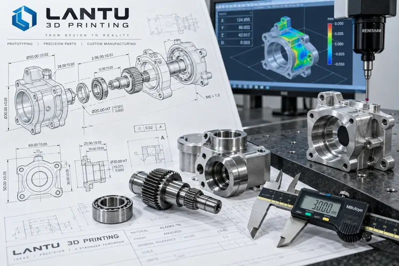
For moving pairs such as snap-fits, hinges, and bearing seats, clearance fits should be preferred, with a designed clearance of 0.05–0.15 mm. Pilot holes for self-tapping threads should be enlarged inversely according to the insert specification. Before delivery, critical dimensions should be sampled using a coordinate measuring machine, or CMM, with an accuracy of ±2 μm. For holes above Ø10, roundness and cylindricity should also be recorded. For small-batch first articles, a full-dimensional FAI report is required. When measured distributions deviate from the target, the compensation factors should be fed back to form a “measure—correct—revalidate” closed loop, instead of relying on manual filing or fitting.
5. Common Misconceptions and Checklist
Misconception one: treating printing accuracy of ±0.1 mm as the assembly tolerance, while actual assembly variation must also include shrinkage and post-processing effects. Misconception two: controlling only individual parts while ignoring the dimensional chain; after five links are stacked, the error can multiply. Misconception three: using sanding to “rescue” interference, which damages geometric tolerances and cannot be reliably repeated. Before production release, verify the following: ① whether the functional clearance has been quantified; ② whether compensation factors are separated by material and direction; ③ whether dimensional chain allocation has been defined; ④ whether the first article has undergone full-dimensional inspection; ⑤ whether rework data has been fed back into the process.
Conclusion
The assembly reliability of 3D printed parts does not depend on post-build fitting, but on early-stage tolerance design and dimensional chain control. Shrinkage should be compensated separately according to material and anisotropy, assembly tolerances should be allocated using the RSS method, and first-article CMM inspection should be used for closed-loop verification. Only by calculating the “0.1 mm difference” risk during the design stage can batch delivery become truly stable.
Submit a model, drawing, image or written notes. Engineers will review material, process, finishing and delivery based on actual use.