
Introduction: Why Defects in Additive Manufacturing Are More Hidden
Unlike traditional subtractive manufacturing or casting, 3D printing—especially metal selective laser melting / laser powder bed fusion (SLM/LPBF)—forms parts through layer-by-layer melting at a microscopic scale. Defects such as lack of fusion, balling, pores, cracks, warping, and powder residues often appear inside or near the surface of the part. A part may look perfectly intact from the outside, yet these defects can become initiation points for failure under service loads. For critical applications such as aerospace hot-section components, medical implants, and functionally integrated parts, “looking fine” is far from the same as “being sound inside.” This is the fundamental reason why nondestructive testing (NDT) has become increasingly important in the additive manufacturing workflow.
1. Why 3D Printing Needs Nondestructive Testing More Than Traditional Processes
First, defect types are more complex: additive manufacturing involves both metallurgical defects, such as pores, lack of fusion, and inclusions, and geometric defects, such as dimensional deviation, uneven wall thickness, and uncontrolled lattice strut diameter. A single inspection method is rarely able to cover all of them. Second, production is often low-volume and high-value: individual parts are expensive, and full destructive sampling cannot be used to statistically evaluate process capability. Instead, each part must be verified across its full volume by nondestructive means. Third, there are quality traceability requirements: customer audits and certification requirements, such as those in aerospace and medical industries, demand quantifiable quality records for every critical part, and NDT data is core evidence for traceability. In lantu3D’s full lifecycle management from blueprint to delivery, nondestructive testing serves as the quality gate for final acceptance.
2. Overview of Mainstream Nondestructive Testing Methods
Visual and optical inspection: This is the most basic method, used for preliminary screening of surface cracks, flash, unremoved supports, and surface roughness. Combined with 3D optical scanning, it can compare external dimensions and generate micron-level surface point clouds, but it is completely ineffective for internal defects.
Liquid penetrant testing (PT): Suitable for cracks and pores open to the surface. It works well for non-ferromagnetic materials such as titanium and aluminum, and is low-cost and fast, but it can only detect surface-breaking defects.
Ultrasonic testing (UT): Capable of detecting internal volumetric defects, but it requires a couplant. For complex geometries, thin walls, and porous structures, acoustic beam coupling is difficult, and quantitative capability is limited.
Radiographic testing (RT): X-rays penetrate the part and form a two-dimensional projection image, enabling detection of internal pores and lack of fusion. However, structural overlap in 2D images makes it impossible to distinguish the depth position of defects, and quantitative analysis is weak.
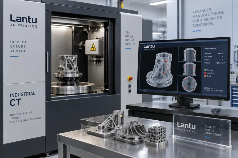
Industrial CT: This elevates the above capabilities from 2D projection to 3D volumetric data. It enables quantitative measurement on any cross-section and from any angle, making it the gold standard for internal quality verification in additive manufacturing.
3. Working Principles and Capability Boundaries of Industrial CT
Industrial CT is derived from medical computed tomography: an X-ray source emits a cone-shaped or fan-shaped beam that penetrates a workpiece rotating around an axis. A flat-panel detector collects hundreds to thousands of projection images from different angles. Reconstruction algorithms, such as FDK, invert these projections into a 3D voxel matrix. The focal spot of microfocus CT can be as small as 1 to 5 microns. Combined with high-resolution detectors, voxel sizes can reach approximately 1 to 10 microns, sufficient to distinguish balling particles and microcracks in additive manufacturing.
It can output three categories of data that can be directly used for release decisions: first, porosity and defect statistics, including defect count, maximum size, and volume fraction, often evaluated according to standards such as ISO/ASTM 52942; second, dimensional and wall-thickness distribution, including internal cavities, cooling channels, and minimum features, with nominal-to-actual deviation color mapping against CAD models; third, structural and assembly verification, such as lattice strut diameter, node connectivity, assembly clearance, and interference.
4. Typical Industrial CT Scenarios in Additive Manufacturing
Porosity release for critical parts: Aerospace and medical parts often specify upper limits for porosity, such as less than 0.2% to 0.5% in critical zones. CT is the only method that can provide overall porosity without destroying the part.
Flow verification of conformal cooling channels: In additively manufactured conformal cooling molds, channels are long, narrow, and internal. CT can verify whether channels are blocked and whether wall thickness is uniform.
Identification of internal defects and lack of fusion: Lack of fusion appears as low-density grayscale areas in CT slices. Combined with threshold segmentation, it can be located and graded, making up for the limitations of overlapping structures in 2D radiography.
Verification of topology-optimized lattices: Strut diameter, node integrity, and pore connectivity in lattice structures can only be checked strut by strut using CT.
5. How Inspection Data Becomes Release Evidence
Inspection is not the goal; release is. The industry has formed frameworks represented by the ISO/ASTM 52900 series, ISO/ASTM 52942 for porosity assessment in metal powder bed fusion, and ASTM F3001/F3302 for titanium and cobalt-chromium alloy materials and process specifications. Enterprises also add customer-specific acceptance criteria, such as maximum defect size, porosity limits, and classification of critical and non-critical zones.
In implementation, it is recommended to solidify NDT results into structured quality records: screenshots of defect locations, porosity values, nominal-to-actual deviation reports, operator IDs, and equipment numbers, all archived by batch. This forms the data foundation for first article inspection (FAI) and small-batch release, and also provides traceable evidence for customer audits.
6. Implementation Points and Common Misconceptions
Inspection timing: Changes may be introduced after printing, support removal, heat treatment, and machining. For critical parts, reinspection in the final state is recommended. Scanning parameters, including tube voltage in kV, current, exposure time, and number of projections—typically 1,000 to more than 2,000—must be calibrated according to material density and wall thickness.
Data volume and cycle time: CT volume data for a single part can reach gigabyte scale and requires professional software, such as VGStudio or Simpleware, for processing. A single scan often takes 30 minutes to several hours, making it suitable for first articles, critical parts, and sampling inspection, but not for blind 100% inspection in every situation.
Common misconceptions: Treating CT as a universal safety net is wrong. It cannot replace process window validation and process control. Microfocus CT has limited penetration for large parts. When lack of fusion has density close to that of the base material, contrast may be low and interpretation must be combined with process parameters. NDT should be the final quality gate, not a cover for process instability.
Conclusion
The competitiveness of additive manufacturing lies not only in its ability to print complex shapes, but also in its ability to prove that every printed part is reliable. From visual screening to industrial CT volumetric quantification, nondestructive testing turns invisible internal defects into a measurable, traceable, and releasable data loop. For companies pursuing full-process control from blueprint to delivery, incorporating NDT into the standard delivery workflow is the true dividing line between quality credibility and commercial trust.
Submit a model, drawing, image or written notes. Engineers will review material, process, finishing and delivery based on actual use.