
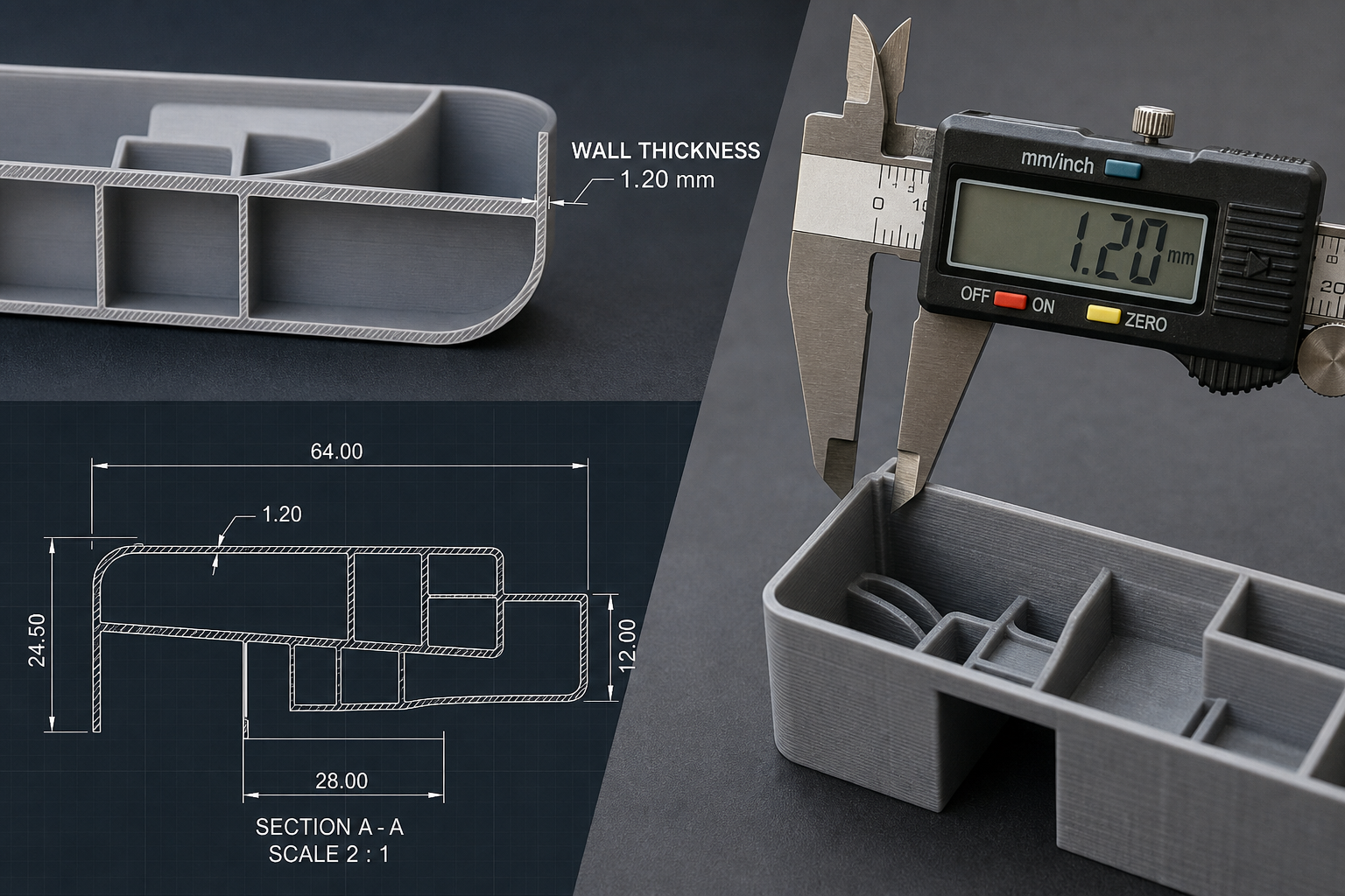
Why Minimum Wall Thickness Is Not “The Thinner, the Better”
In 3D printing design, minimum wall thickness determines whether a part can be formed reliably, removed safely, depowdered, post-processed, and ultimately perform with structural integrity in service. Many print failures are not caused by a model being “unprintable,” but by wall thickness that only meets the software’s theoretical lower limit without accounting for engineering factors such as material shrinkage, interlayer bonding strength, support dependence, thermal distortion, and transport damage. Taking the same thin-wall lattice part as an example, increasing wall thickness from 0.8 mm to 1.2 mm often significantly improves print success rate, post-processing yield, and bending stiffness; however, making the wall even thicker will increase weight, material cost, and internal stress. Therefore, minimum wall thickness should be defined by three criteria—printable, post-processable, and serviceable—rather than by equipment specifications alone.
- Design thresholds must consider forming, post-processing, and service loads at the same time, not just whether the part can be printed.
- The most common failures in thin-wall parts include warping, edge breakage, delamination, powder-removal cracking, and transport-induced deformation in resin parts.
- From an engineering perspective, it is recommended to reserve a 20%–50% safety margin above the process minimum, especially for load-bearing parts and long-span structures.
Recommended Minimum Wall Thickness for SLA Photopolymerization
SLA offers high surface accuracy and excellent detail reproduction, making it well suited for thin-walled housings, fluid channels, transparent prototypes, and dental models. However, the mechanical properties of SLA parts vary greatly depending on the resin type. Standard resins are typically relatively brittle, and thin walls are more prone to cracking during support removal, post-curing, and minor impacts. In general, the recommended non-load-bearing wall thickness for standard SLA resin is no less than 0.8 mm. For long, slender structures, parts with significant overhangs, or locally perforated structures, it is advisable to increase the thickness to 1.2–1.5 mm. For tough resins and high-temperature resins, although the material toughness is better, post-curing shrinkage and distortion risk still remain, so thin-wall parts should still not be thinner than 1.0 mm.
In a practical case, a medical device housing originally designed with a 0.6 mm wall thickness was printed in standard resin and developed local cracking during support removal, with edge warpage of about 1.2 mm after post-curing. After increasing the wall thickness to 1.2 mm and converting large flat surfaces to ribbed structures, the finished-part acceptance rate increased from less than 70% to nearly 100%. For hollow SLA parts, drain-hole size and placement must also be considered; otherwise, trapped resin will add local weight and induce distortion.
- Standard SLA resin: recommended wall thickness ≥ 0.8 mm; high-reliability housings are recommended to be 1.2 mm or thicker.
- Tough/high-temperature resins: recommended wall thickness ≥ 1.0 mm; long-span areas are recommended to be 1.5 mm.
- Hollow parts must include drain holes to prevent retained resin from causing local bulging or post-curing deformation.
Minimum Wall Thickness Thresholds for SLS Nylon Powder Processes
SLS is one of the most suitable processes for complex thin-wall structures because the powder bed provides natural support, enabling the printing of internal cavities, nested structures, and complex channels. For common PA12, the theoretical minimum wall thickness can be around 0.6 mm, but engineering practice usually recommends no less than 1.0 mm. If the part is relatively tall, has a large area, or needs long-term service, 1.2–1.5 mm is recommended. For PA11 or glass-fiber-reinforced nylon, the material toughness and stiffness are higher, but because thermal shrinkage and warp sensitivity differ, thin walls are not necessarily more aggressive than PA12; stable designs should still prioritize 1.2 mm or above.
It is important to note that whether an SLS thin wall can be successfully produced depends not only on wall thickness, but also on whether the wall has sufficient closed-loop geometry, adjacent supporting structures, and wall length. For example, a 200 mm-long, 1 mm-thick flat plate may be printable in SLS, yet it can still exhibit wavy warping during cooling. In an automotive duct project, a PA12 duct with an original wall thickness of 0.8 mm showed local collapse in large flat areas. After increasing the wall thickness to 1.3 mm and adding 2 mm-high reinforcing ribs, dimensional stability improved significantly, and the assembly gap was reduced from 1.5 mm to within 0.4 mm.
- PA12 SLS: engineering recommendation is 1.0–1.2 mm, and 1.5 mm for reliable housings.
- Long flat surfaces and wide panels should be ribbed rather than simply thickened to prevent cooling-induced warping.
- Internal powder removal requires careful opening-size design; overly thin closed structures carry a high post-processing risk.
Key Wall Thickness Design Considerations for FDM
FDM is especially sensitive to minimum wall thickness because it is directly constrained by nozzle diameter, line width, layer height, and toolpath planning. For a 0.4 mm nozzle, a single extruded line width is typically about 0.42–0.48 mm, so wall thickness should be planned in multiples of the line width. A common engineering recommendation is at least two perimeter walls, meaning a wall thickness of no less than 0.8 mm. A more robust design is 1.2–1.6 mm, especially for materials prone to warping such as ABS, PC, and PETG. If a 0.6 mm nozzle is used, the lower limit can be increased to above 1.2 mm to ensure stable extrusion and interlayer bonding. Another risk of thin walls is low interlayer strength; parts can easily crack along layer lines during press-fit assembly, snap-fit engagement, or screw fastening.
A common engineering issue is snap-fit design. In one consumer electronics housing, the original wall thickness was 1.0 mm and PLA was used for printing, but the snap-fit root cracked during assembly. Analysis showed that, in addition to the thin wall, the fillet at the root of the snap-fit was only 0.3 mm, and the layer orientation matched the direction of the applied load. The final solution was to increase wall thickness to 1.6 mm, enlarge the root fillet to 0.8 mm, and adjust the print orientation so that the load direction avoided interlayer separation as much as possible. The yield improved significantly. Another key point for FDM thin-wall parts is that wall thickness should ideally be an integer multiple of the nozzle line width to avoid half-line walls that cannot be fully filled.
- 0.4 mm nozzle: recommended minimum wall thickness ≥ 0.8 mm; common engineering values are 1.2–1.6 mm.
- Wall thickness should preferably be an integer multiple of line width to reduce weak zones caused by gaps, over-extrusion, or under-extrusion.
- Snap-fits, bosses, and press-fit features should not be evaluated by outer wall thickness alone; local fillets and load direction relative to layer orientation also matter.
Thin-Wall Limits and Thermal Distortion Control in SLM Metal Printing
The minimum wall thickness in SLM metal printing is closely related to thermal management. Metal materials conduct heat quickly and generate significant residual stress, so thin walls are highly susceptible to thermal warping, edge curl, and even local melt collapse during the build. Different metals behave very differently: aluminum alloys are typically more sensitive to thermal distortion, so thin walls are generally recommended to be no less than 1.0–1.5 mm; 316L stainless steel is relatively stable, and a common engineering lower limit can be 0.5–0.8 mm, but if the part includes long thin walls, cantilevers, or complex lattices, 1.0 mm or more is still recommended; titanium alloys offer high strength but require a strict process window, so thin walls are usually recommended to be ≥ 0.8 mm. In actual production, wall thickness must satisfy not only printing requirements but also dimensional springback after heat treatment.
In one aerospace lightweight bracket project, 316L was used for printing. The first version had a wall thickness of 0.6 mm. The geometry near the base plate formed reasonably well, but the upper thin-wall region exhibited local waviness and edge burn-off. After adjusting the wall thickness to 0.9 mm and adding connecting ribs and optimizing the scan strategy, part deformation dropped from 0.9 mm to about 0.3 mm, and the machining allowance became much more controllable. When designing thin-walled SLM parts, the contact area of the lower supports must also be considered: too few support points can damage the thin wall during part removal, while too many will increase post-processing marks.
- 316L: engineering recommendation 0.8–1.0 mm; complex structures are recommended to be 1.2 mm.
- Aluminum alloys: recommended wall thickness ≥ 1.2 mm; avoid large unsupported thin plates whenever possible.
- Thin-walled metal parts must be designed in conjunction with scan strategy, support density, and dimensional springback after heat treatment.
Wall Thickness Recommendations by Process and Material
Wall thickness design cannot be treated as one-size-fits-all; it must be evaluated in combination with both the process and the material. For the same nominal thickness, SLA is more sensitive to brittleness and post-curing, SLS to powder support and cooling-induced warping, FDM to nozzle extrudability and interlayer strength, and SLM to thermal stress and support removal. If the part is used only for appearance verification, the wall thickness can be close to the process minimum. If it is used for low-volume trial production, functional validation, or final delivery, it should be clearly above the minimum. In general, it is recommended to distinguish between “functional wall thickness” and “process minimum wall thickness” in the design drawing; the two should not be confused. This helps control weight while leaving sufficient margin for production.
- Standard SLA resin: starts at 0.8 mm, recommended 1.2 mm; tough resins are recommended at 1.0 mm or above.
- SLS PA12: 0.6 mm is printable, but engineering practice recommends 1.0–1.5 mm.
- FDM with a 0.4 mm nozzle: starts at 0.8 mm, recommended 1.2–1.6 mm; a 0.6 mm nozzle is recommended at 1.2 mm or above.
- SLM stainless steel: starts at 0.5–0.8 mm; engineering recommendation is around 1.0 mm; aluminum alloys are recommended at 1.2 mm or above.
How to Avoid Failures Caused by Insufficient Wall Thickness During the Design Phase
The most practical approach is to make wall-thickness verification a standard part of the modeling workflow. First, confirm the part’s purpose: is it a presentation piece, an assembly-validation part, or a load-bearing functional component? Second, confirm the build orientation, because the strength of a 1 mm wall can differ greatly between across-layer and along-layer directions. Third, consider the post-processing route, such as blasting, dyeing, infiltration, support removal, heat treatment, or machining; any of these steps can weaken a thin wall. Fourth, leave tolerance margin, especially for insert holes, slots, and sealing surfaces; thin-wall parts should not be designed directly to the absolute nominal limit.
Before sending parts out for sampling, it is recommended that companies perform three checks: first, verify whether the thinnest wall is below the selected process minimum; second, verify whether long flat surfaces lack reinforcing ribs; third, verify whether there are sharp corners, holes too close to the wall edge, or local stress concentrations near thin-wall regions. For
Submit a model, drawing, image or written notes. Engineers will review material, process, finishing and delivery based on actual use.